Tool/software:
Q1.
https://www.ti.com/lit/ds/symlink/iwrl6432aop.pdf
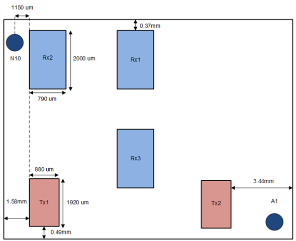
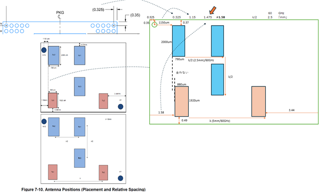
7.14 Antenna Positions Figure 7-10 shows the placement and relative spacing of the antennas
The distance dimension from the IC package edge to the antenna does not match. Can the dotted line indicating the positional relationship between RX2 and TX1 be ignored?
Q2. Can you provide the antenna structure diagram, including:
- Material info
- Thickness
- Distance from the GND plane
Q3. Can you provide any recommendations or precautions for customer PCB design.
(e.g., surrounding pattern shapes, distance from other components, etc.).
Not much info in the "HW Design Guide Bring up, Schematic and Layout checklist xWRL6432AOP-1-2.xlsx."