Other Parts Discussed in Thread: AWR2944P, AWR2243BOOST, AWR2243
Tool/software:
Hey,
Using mmWave SDK on the AWR2944P DSP, we first run FFT, CFAR and angle-estimation on the DSP itself. How can we then define a custom UDP payload format over Ethernet so that the Jetson receives exactly our processed data? For example, I need to package each detected target’s [range, Doppler, angle] triplet (12 bytes) plus a user-defined 4 byte timestamp, instead of the default point-cloud TLV. What API calls or cfg files control that?
Does the AWR2944P use the same host-side mmWave Link (TLV-based) API as the AWR2243BOOST? Are there any changes in function names, parameters, or supported TLV types that I should be aware of when moving my Jetson code from the 2243 to the 2944?
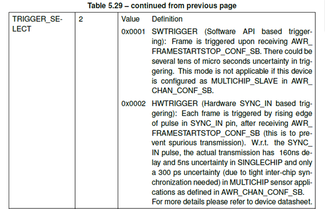
On the AWR2944P EVM, we couldn’t find a dedicated SYNC-IN pin. GPIO_28 is tied to the on-board button (SW1). Can we remove SW1 and wire an external trigger cable into GPIO_28 for multi-chip synchronization? We currently drive a 3.3 V pulse from a Jetson into the AWR2243BOOST successfully and need the same setup on the AWR2944P.
Does the programming we do on the AWR2944P EVM survive powercycling? so we dont need to load a .cfg each time we restart the board.
The final question is just a observation i noticed in the AWR2944Ps user guide, I saw in a picture that the AWR2944P had a DCA1000 connected, does this serve any purpose? Since the AWR2944P EVM has it's own ethernet port and can send the UDP packets to a external processor by itself.
//Emil