IWR6843AOP: GPADC use and internal temperature measurements

Part Number: IWR6843AOP

Tool/software:

Hi,

I am using IWR6843AOP and tried to measure voltages with GPADC 1 to 6, using as example the file shared in this post

 https://e2e.ti.com/support/sensors-group/sensors/f/sensors-forum/1016216/awr6843aop-awr9843aop-gpadc?tisearch=e2e-sitesearch&keymatch=iwr6843aop%252525252520gpadc# 

My GPADC4 channel does not match the actual voltage measured with a multimeter on my custom PCB.

By reading the datasheet I found the following : 

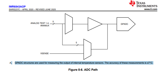
"GPADC structures are used for measuring the output of internal temperature sensors"

Does this means that I cannot monitor the internal temperature and have an external voltage measurement using the GPADC ?
Are those measurements conflicting ?
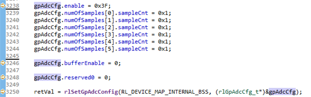
The voltage measurements are triggered by : rlSetGpAdcConfig(RL_DEVICE_MAP_INTERNAL_BSS, (rlGpAdcCfg_t*)&gpAdcCfg);
The temperature measurement is triggered by : rlRfGetTemperatureReport(RL_DEVICE_MAP_INTERNAL_BSS, (rlRfTempData_t*)&gMmwMCB.temperatureStats.temperatureReport);

Thank you for your support.

  • Hello!
    We are looking into your query. Please allow us some time to respond.
    Thanks.

  • Hi,

    You can monitor external voltage using the GPADC. What is the voltage you are trying to measure using the GPADC pin? Kindly ensure the voltage level is within the ADC buffered input voltage range (0.4V - 1.3V). You can use voltage divider circuit to scale your voltage down as an input to the GPADC pin. The reading of GPADC pin can be scaled accordingly wrt resistor divider to corelate the measurements.

    Regards

    Ankit

  • Dear Ankit, 
    Thank you for your reply.

    The voltages are all around 1.0V except the one connected to channel 4 which is 1.8V.
    I read from the datasheet that the maximum input range is 0-1.8V without the use of the optional buffer.

    1. How can I disable this buffer ?
    2. Can those external voltage measurements be in conflict with the internal temperature measurement ?


    Sincerely,
    Vic

  • Hi,

    Please allow me couple of days' time to check this internally. The general recommendation is to the within the ADC buffered input voltage range. 

    Regards

    Ankit

  • Hi Vic,

    1. If you want to use the unbuffered input, you can set the "SIGNAL_BUFFER_ENABLES" of the input bit to 0 for the corresponding GPADC. Otherwise, use GPADC6 where the internal buffer is not available.

    2. No, the external voltage measurements will not be in conflict with the internal voltage measurements. 

    Regards

    Ankit

  • I tried the following settings to disable the buffer but my measurement is still 1.2V instead of 1.8V.
    I guess this is the way to disable the buffer via the API ?

    Also I could not find the document that provides this register description SIGNAL_BUFFER_ENABLES, nor in the TRM nor in the datasheet.

  • Hi Vic,

    I have passed the thread to software expert; please allow us couple of days to respond.

    Regards

    Ankit

  • Hello Vic.

    Also I could not find the document that provides this register description SIGNAL_BUFFER_ENABLES, nor in the TRM nor in the datasheet.

    This is not a register; it is a field for a struct used to configure the GP ADC via the firmware.  Information on this struct is found in the interface control document, which is where Ankit got the screenshot from.

    I tried the following settings to disable the buffer but my measurement is still 1.2V instead of 1.8V.
    I guess this is the way to disable the buffer via the API ?

    This looks correct; is it not configuring the GPADC as expected?  Also where in the code are you calling this API?

    Sincerely,

    Santosh

  • Hi Santosh,

    I am currently trying this on a modified mmWave demo.
    I call the first rlSetGpAdcConfig at the end of the initTask and then call this function periodically every 100ms, based on external UART request. The input parameters of the function remain the same always.

    Thanks for your support.

  • Understood.

    I assume that this doesn't seem to do the trick; do you have low power enabled?  It may be that with every time the device comes out of deep sleep this setting could be reset.  If you do have low power enabled, can you try setting lowPowerCfg 0 in your configuration file and checking that the voltage is correct?

    Sincerely,

    Santosh