PGA970: PGA970

Part Number: PGA970
Other Parts Discussed in Thread: UNIFLASH

Tool/software:

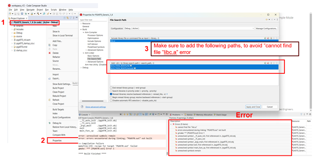
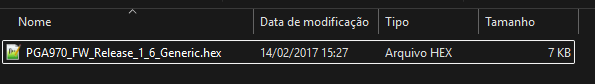
Hi, I managed to download the files, but I'm unable to compile using CCS 20.2.0:


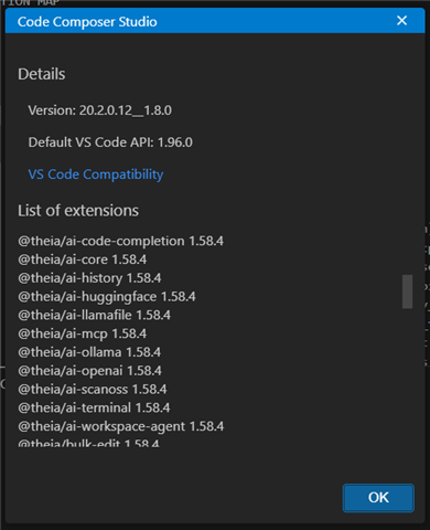
Is this software the right one for compiling and recording the sample program?

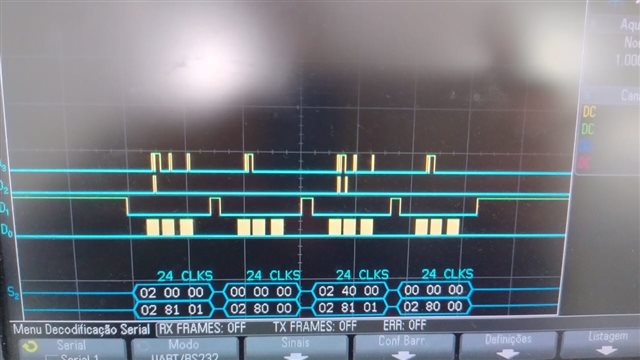
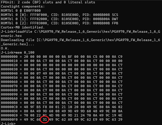
I also tried recording directly using J-Link and OpenOCD, but I couldn't record the file, only read a few bytes, and even then I don't know if it read correctly:

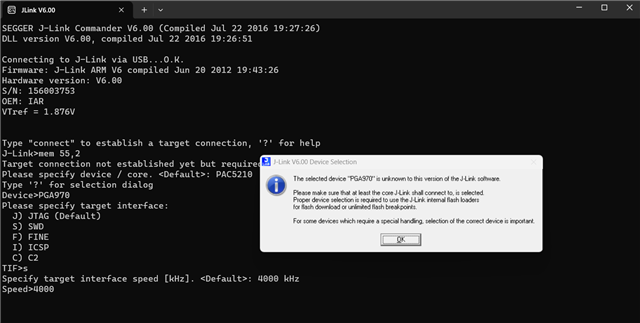
What is the correct way to do this, considering that we only have J-Link available as a recording device?

  • Hi Felipe, 

    I believe the example firmware was compiled using version CCS v.6. My team prefers CCS v12.8. 

    Here are some common issues:

    • You did not install the PGA feature set when you downloaded CCS
    • You did not copy rtsv6M0_T_le_eabi.lib into the following path: C:\ti\ccs1281\ccs\tools\compiler\ti-cgt-arm_20.2.7.LTS\lib
      • Since you're using CCS v20, the path will look a little different
    • You did not initialize the device definition:
      • You need to delete some files after updating the properties
    • Your error is "Program "make" is not found in PATH"
    • Your error is "fatal error: cannot open source file "pga970_platf.h"
    • Your error is "unresolved symbols remain"

    Looking at their website, it looks like J-Link does not support PGA970.

    I cannot support questions about non-TI debuggers. Uniflash with an XDS110 debugger is TI's preferred tool for loading firmware to PGA970. You can find more information here

    Thanks,

    Maggie

  • Great, very good!

    I installed version 12.8.1, followed your recommendations, managed to compile it, recorded it with J-Link, and it is already generating a 5KHz sine wave.

    Are there any examples of communication and libraries for SPI that send the LVDT reading?

    Thank you very much.

  • Hi Felipe, 

    We don't have any examples beyond the example firmware, which I believe you already have. 

    There are several ways to read the LVDT reading. 

    1. If the PGA970 microcontroller is in reset (so the compensation algorithm and firmware is not running), then you can use SPI to read directly from the demodulation outputs (DEMODx_DATA and DEMODx_PHx). If the microcontroller is in reset, then you will have to use an external microcontroller if you want to linearize the demodulation outputs. 
    2. If the PGA970 microcontroller is running (so the compensation algorithm is running), then you can the compensated data over SPI using the COMBUF registers.

    You can refer to 7.3.1.12.1 Accessing PGA970 Memories While the Microprocessor Is Running for more details on the COMBUF, but in short, there are only a couple of registers which the user can access while the PGA microcontroller is running. The user can write firmware to perform certain actions while the COMBUF receives certain commands. The following registers are the most useful:

    • COM_MCU_TO_DIF_Bx, which is read by the digital interfaces
    • COM_DIF_TO_MCU_Bx, which is written by the digital interfaces

    As an example, you could write firmware which performs the following:

    1. Define COMBUF command 0xAAAA, which instructs the microcontroller to send the compensated data out over SPI until a STOP command is issued. 
    2. Define 0xFFFF as the STOP command
    3. If no command is written to COM_DIF_TO_MCU_Bx, then nothing happens. The compensation algorithm runs as you have written it in the firmware. 
    4. If 0xAAAA is written to COM_DIF_TO_MCU_Bx, then at the end of algorithm loop, the microcontroller will write the compensated value to COM_MCU_TO_DIF_Bx. The user can read this register over SPI to read the compensated value. 
    5. The compensated value is repeatedly written to COM_MCU_TO_DIF_Bx until the user writes 0xFFFF to COM_DIF_TO_MCU_Bx. 

    Thanks,

    Maggie

  • Hi Maggie,

    I recorded exactly this file:


    But I can't get a response from SPI.
    I followed the examples:


    But in no reception did I get 0x05 at the beginning of the SPI packet.

    What could be wrong?

  • I followed this example exactly:

    Here is the FRAM memory reading via the J-Link recorder:

    Commands sent:

    Oscilloscope reading:

    Did not return the expected value of 0x31.

  • Hi Felipe, 

    That example is an error in the datasheet. To read from FRAM, first you need to select the FRAM page address by writing to the FRAM_PAGE_ADDR register (0b010 0001 1000 1 aaaaaaaa xxxx; a= desired page address, and x=don't care). Then you have to send a read command (0b100 aaaaaaaa 0 xxxxxxxxxxxx). The register data will be available on the next SPI transaction. 

    Thanks,

    Maggie

  • We found an error in the SPI configuration, after fixing it we started receiving 0x05 as an answer, below the images from the SPI master firmware and digital analyzer showing the SPI communication.

    Even with those instructions, i'm receiving 0x05 as answer and 0x00 0x00 as data, we need an example that answers the LVDT digital conversion from the firmware below.


    Using a modified example firmware, we've managed to measure the LVDT reading on the DAC pin and it worked just fine, but, using the original example, we need to read the data straight from the registers via SPI, can you help with a step by step guide showing the bits commands to get that answer?

  • Hi Felipe, 

    When you are sending SPI read/write commands to PGA970, is the PGA970 microcontroller in reset, or is it running? If it is in reset, then you should be able to read the demodulator outputs using the instructions I shared yesterday. For example, if you wanted to read DEMOD1_DATA (which is 32b), you would use the following commands:

    1. 0b000 00010000 0 xxxx xxxx xxxx (command to read registers 0x10 and 0x11)
    2. 0b000 00010010 0 xxxx xxxx xxxx (command to read registers 0x12 and 0x13, register data from 0x10 and 0x11 will be available on the 2nd and 3rd bytes of the MISO)
    3. command doesn't matter as long as it's a valid SPI command (register data from 0x12 and 0x13 will be available on the 2nd and 3rd bytes of the MISO)

    x = don't care

    If you want to read the register data while the microcontroller is running, you have to use the COMBUF registers, which requires firmware. I don't think the example firmware implements any commands to interact with the COMBUF registers. You can see the datasheet for more details. 

    Thanks,

    Maggie