Tool/software:
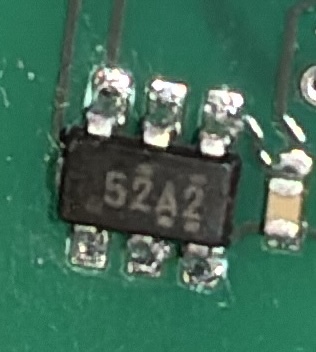
Our device has two TMAG5273s: one is an A2 variant, and the other is a B2.
I wrote a driver to communicate with them using the 1-byte, 16-bit read mode for X, Y & Z, and everything worked fine.
I then turned on CRC generation, and added code to check the CRC based on information from the data sheet. For this mode, it states the CRC is calculated from the "command byte and the data sent in the current packet", though doesn't define what "command byte" is. Assuming this meant the secondary address + the read bit, I used 0x6B and 0x45 for byte 0 for the A and B chips, respectively.
For the B chip, this worked fine. However, for the A chip, my calculation never matched the chip's (and I double checked this with an online CRC calculator). After trying various other values for byte 0, I wrote code to try all possible values, and came up with 0xBC. I used this value in the driver...and it worked perfectly!
So on the one hand, the problem is solved. But on the other hand: why is this number used? I could not find any mention anywhere of this value. Where does it come from?
To give a real example, here is some real data returned from the A sensor (X, Y & Z values + CONV_STATUS + CRC):
0x00 0x0c 0xff 0xeb 0x00 0x0f 0x01 0x11