Tool/software:
Q1) About the meaning of PD
The manual states that PD stands for "Peak Detector".
However, I am not sure what a Peak Detector actually is.
Could you please explain what a Peak Detector is?
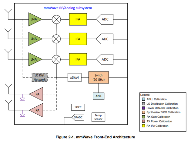
Q2) About the meaning of LODIST
The manual describes LODIST_BIAS_CODES as "Lo Distribution bias current control codes".
However, I am not sure what "Lo Distribution" refers to.
Could you please explain what Lo Distribution means?
Q3) About the PM temperature sensor
Does "PM" stand for "Power Management"?
Q4) About the DIG temperature sensor
Could you please tell me what "DIG" stands for?
[Referenced]
MMWAVE_L_SDK_05_05_03_00
mmwave_dfp_interface_control_document.pdf