AWR6843: AWR6843 Custom board raw data capture wtih DCA1000

Part Number: AWR6843

Tool/software:

Hi

I encountered an issue while attempting to log data by connecting the custom board to the DCA1000.

I checked the question below.

AWRL6432: Interface with DCA1000 for raw data capture - Sensors forum - Sensors - TI E2E support forums

Therefore, as above

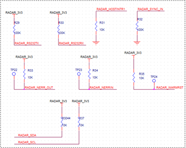
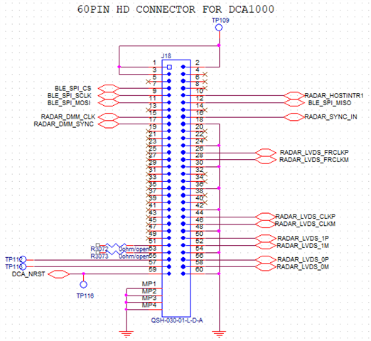
SPI (x5)/ RS232 (x2)/ RESET (x1)/ LVDS (x4) / LVDS CLK (x4)
I am using the above signals on the custom board.
The RS232 is connected via a CP2105.

Booting proceeded with sop[2:0] = 110.
Originally intended for communication with other MCUs via the SPI signal, the absence of this indicates successful entry into DCA1000 mode.

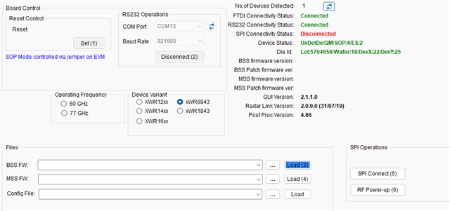
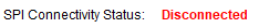
However, SPI is displayed as disconnected.


The reference document I consulted is DCA1000 mmWave Studio User Guide.

and I confirmed that the SPI connection is established when using the 6843ISK.

Are there any other considerations on the custom board besides the signals required for connecting to the SOP and DCA1000?

Thanks.

  • Hi, there:

    Thank you for reaching to us.  One of our hardware expert will get back to you in a day or two.

    Best,

    Zigang

  • Hi,

    Can you please check if the pull ups are given correctly. Can you share a snap of the setup which you are using.

    Regards,

    Sreedeep

  • Hi,

    Please tell me which pull-up to check.

    Firstly, as above, the difference is that there is no SPI CS pull-up. (This is because it is communicating with the MCU [slave] and has an internal pull-up.)
    Additionally, via the switch on the custom board, SOP[2:0] was set to 011 (debug), and the signal was verified.
    The signals on the custom board connected via the DCA1000 are identical to those in the attached photograph of the written post.

    [GUI]

    The AWR6843ISK and DCA1000 have been successfully connected. When attempting to apply this successful method to a custom board, the above issue occurred.

    The mmwave_studio_user_guide states:
    Once the MSS firmware boot up is complete, Click SPI Connect.

    - Is this related to the above issue?
    - How are MSS power-up asyc events transmitted via which signal, and what sequence do they follow?

    Ask for more details and we'll let you know.

  • Hi,

    For connecting to studio, we use DCA1000 interface. During this time the device won't be communicating with MCU. Hence CS pull up is required in this case.

    Regards,

    Sreedeep

  • I will test it tomorrow. So, will the above error, mss power up async problem be solved?

    thanks.

  • Hello,
    The test results indicate that the pull-up issue is not related to the CS pin.
    Furthermore, to prevent SPI communication with the MCU (slave), we also disconnected the SPI connection to the MCU side and conducted testing.

    Under what circumstances does the above error code appear?

  • Hi,

    Can you share the schematic of the design so that we can take a look at it.

  • hello
    Sometimes the spi connection succeeds and sometimes it fails, even if we run the same test environment.
    I haven't found the reason yet. EVK also fails intermittently.
    Is it something very sensitive to the SPI timing?
    Is there a problem with the schematic since it sometimes succeeds?