AWR2243: A 0.4 deg random interference is observed after enabling IQMM

Part Number: AWR2243

Tool/software:

Team,

Customer observed a problem after enabling RX IQMM option in rfInitCalib.calibEnMask in mmwave_link_spi_22xx.c

The phenomenon is a 0.4 deg random interference is observed on a target with 250 meters. If they disable the RX IQMM option, this interference will not be observed.

Now we want to know:

1. Will the RX IQMM option cause above problem?

2. I believe we can disable the RX IQMM option in real mode, can we disable the IQMM option in complex mode?

Regards,

Shawn

  • Hi Shawn,

    By 'interference' do you mean a spur is observed in the range FFT spectrum?  Can customer provide a capture showing the issue?

    IQ mismtach enable should not cause any spur or interference.

    I think you can disable IQ mismatch calibration in both real and complex modes (I will confirm).

    regards,

    Ali


  • Hi Ali,

    This picture can be used as a reference.

  • Hi Shawn,

    There is high variability in the data, and the difference is only 1 dB.  Can you use some averaging to 'smooth' out the spectrum.  Also, are both plots using the same number of samples?  In the 2 plots looks like spectrum resolution is different between them.

    regards,

    Ali

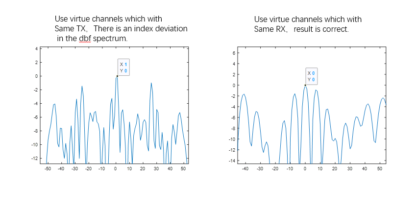
  • In the figure, the x-axis represents the angle(°), and the y-axis represents the power spectrum (in dB). Our radar is a 6T8R system. Its virtual channels are denoted as TX1-RX1, TX1-RX2, ..., TX6-RX8.

    Test scenario: The radar is calibrated once in a dark room environment. After calibration, the radar is restarted. In the same environment, a test target with an angle of 0° is set.

    Previously, we enabled RX IQMM according to the default settings and restarted the system multiple times for testing. There was a probability of over 15% that the situation shown in the figure would occur:

    (1)The figure on the left is the power spectrum obtained after 2D-FFT, using the 5 virtual channels TX1-RX1, TX1-RX2, TX1-RX3, TX1-RX4, and TX1-RX5 to perform DBF. The peak of the spectrum is at the 1° position.

    (2)The graph on the right shows the power spectrum obtained by using the 4 virtual channels TX1-RX1, TX2-RX1, TX3-RX1, and TX4-RX1. The peak of the spectrum is at 0°.
    From the measurement angle results, there is an error in the phase difference between the receivers, which causes deviations in the measurement angle results.

    After we shut down the RX IQMM, we repeatedly restarted the system 200 times under the same conditions. Since then, this deviation has never occurred again.

  • Hello,

    I will review this information, and provide feedback ASAP.

    regards,

    Ali

  • Hello,

    Are you using both boot-time and periodic run-time RX IQ MM calibrations?

    You mentioned calibrations done in dark-room - do you restore those calibrations during run-time?  

    Since you mention that this error happens 15% of the time upon start-up, are all tests in dark-room (that is no external interference).

    regards,

    Ali

  • 1、We have not enabled runtime calibration.

    2、We don't restore;

    3、yes

  • Hi,

    Sorry for delay.

    I am checking with other team members about this. Are you using T.I EVM?  Or this is your own design.

    0.4 deg seems like a very small error.  What is the angular resolution that you are trying to achieve?

    regards,

    Ali

  • Hi,

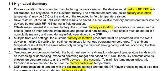
    I wanted to share the document:  Cascade Coherency and Phase Shifter Calibration

    This applications note points to a calibration strategy specially for cascaded systems. See summary below for summary.  Please review this document and I can clarify any questions you may have.


    regards,

    Ali