AWR2E44PEVM: AWR2E44 ADC input current value

Part Number: AWR2E44PEVM

Tool/software:

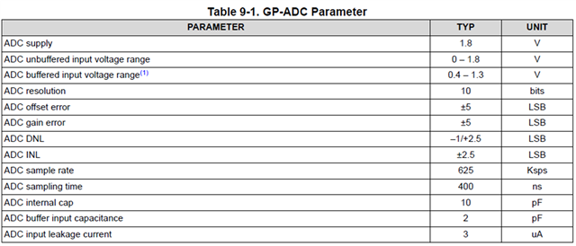
We are planning to use ADC pins 5 and 6 for voltage monitoring. Could you please advise on the recommended input current specification and input capacitance? The leakage current is expected to be designed below 5 µA.

Please check unbuffered condition and buffered condition.

  • Hello,

    Since the GPADC is only intended to measure DC voltage the input current will be equal to the ADC input leakage current (~3uA).

    Regards,

    Adrian

  •   Thank you for your response. What is the recommended ADC input impedance value for calculating the input current? Also, is there a suggested current-limiting resistor value?

  • Hello,

    The GPADC is a voltage mode ADC not current mode ADC, so you should not be thinking about it in terms of current. When a DC voltage is applied the input will be seen as high impedance. There is no need to use a current limiting resistor. However, a resistor divider should be used if you intend to measure a voltage which exceeds the specified input voltage range.

    Regards,

    Adrian 

  •   Thank you for your response. So, for a simple circuit intended only for external voltage monitoring, I understand it can be composed of just R1, R2 for voltage division and C1 for filtering or sampling time. However, what concerns me is that to calculate the voltage division accurately, we might need to know the input resistance (Rin) of the ADC, right? (e.g., R2||Rin / (R2||Rin + R1)). Is this the same for both buffered and unbuffered ADCs? Also, There is any ESD diode in GPADC module?

  • Hello,

    Yes, there is are ESD structures on the GPADC pins.

    The input resistance will be higher in buffered mode. We recommend to always use buffered mode on the GPADC.

    To properly size the resistors, you should choose a divider value such that the impact of the leakage current is negligible. For example, if you choose a 1M resistor, when you have 3uA of leakage this will result in a significant additional voltage drop across the resistor. If you choose something in the 10-20k range, the drop becomes negligible and you can assume that the voltage at the GPADC pin will be equivalent to your desired voltage set by the divider. The intention of these pins is to check for critical faults in the power supply and should not be used to try to measure the voltage with microvolts of precision.

    Regards,

    Adrian  

  •  The voltage range we need to monitor is quite wide, so the buffered mode cannot cover this range. Are there any issues that may arise when using an unbuffered ADC, and could you recommend an example circuit?