LDC2112: LDC2112 power-up calibration

Part Number: LDC2112
Other Parts Discussed in Thread: LDC2114, LDC0851, LDC3114

Tool/software:

Hello,
I have an application where we check the presence of a metal target in front of the sensor LDC2112. We discovered the issue, that the sensor behaves differently depending whether the target was present or not during the power-up. Further investigation showed, that when there is a target during power-up, it seems that the sensor calibrates to it as a background level, and even a tiny increase in distance turns the output off, while it should be still on for a bit longer (when powering-up without the target). What can I do to mitigate that dependency?

  • Hello Jakub,

    This sounds like the baseline tracking function of the device.  See section 8.1.9 of the datasheet for more information.  If you power up with the target present, this will be used to determine the baseline measurement.  On the LDC2114, there is no way to turn off baseline tracking.  For a similar device, the LDC3114 also allows for "raw" mode where baseline tracking is disabled.  If you are not looking to use baseline tracking, you could also look at the LDC131x and LDC161x or even LDC0851 for a simple switch type device.

  • Is it possible to reset that tracking acquired during power-up? We have already manufactured dozen of PCBs with that chip, but it fails to operate when the target is present during power-up. I can remove the target and with fast tracking enabled it fixes itself, but I need to know if the target is present straight after the power-up of the sensor

  • See the post below that discusses adjusting the base increment rate which could speed up the normal operation.

     LDC2114: turn on and calibration  

    Also, section 5.2 of the app note below discusses conditions where the baseline is reset.  

    https://www.ti.com/lit/an/snoa993a/snoa993a.pdf 

  • The baseline increment does not help, because the target is still there, and sensor is not detecting it. It would be great to acquire the raw data

  • Unfortunately, this is not an option on the LDC2114.  You would need to switch to one of the devices mentioned above for raw data.

  • We have bought LDDC3114. I am trying to use it in the raw mode, but I can't get interrupts on INTB output running. I have sensors connected to channels 0 and 1, channels 2 and 3 are not connected and disabled in the ENABLE register. No matter what I set in the INTPOL register, interrupts are not triggering

  • Jakub,

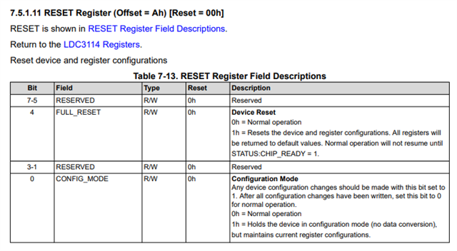
    In raw mode, the interrupt should be asserted when new data is available.  Be sure you are putting the device in to config mode before making any changes to registers.  After the new register changes are complete, you can set this back to normal operation.    

  • I believe that registers are set correctly, because the sensor reacts to various settings, and reading these registers confirms correct values. The bigger problem we have encountered is that the raw signal change is around 1-2% when the target approaches the sensor. This is very little. Can you recommend any solutions to increase the sensitivity? 

  • Jakub,

    See the application note below.  The biggest influence on the sensitivity will be the coil size and distance to the target.  A good rule of thumb is that you can acheive good resolution when the target is a maximum of 50% of the diameter of the coil.  For example, a 10mm coil will work well up to about 5mm distance.  

    Sensor frequency can also have some impact.  For longer range applications, use a lower frequency.    

    The target size and conductivity will also have an effect.  Target size should be at least as large as the coil.  Higher conductivity metals will also show more of a change in inductance.  Copper and aluminum work well.

    https://www.ti.com/lit/an/snoaa76/snoaa76.pdf