AWRL6844: AWRL6844 antenna calibration question

Part Number: AWRL6844

Tool/software:

Dear TI Team,

I have a question regarding antenna calibration for the AWRL6844. Our team is using the 6844-related application in radar_toolbox_3_20_00_04.

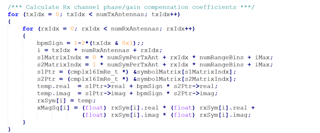
In the range_phase_bias_measurement.c file, why is the collected data multiplied by the bpmsign value (as shown in Figure 1)? All configurations—including ID, CPD, and SBD—are using TDMA mode.

Additionally, could you confirm whether the loop in Figure 1 is incorrect? Based on the current implementation, it seems that the index does not change according to the Tx antenna index.(From RadarCube)

Lastly, why does the calibration is not allowed when clutter removal is enabled? The data used is from RadarCube—could this be affecting the results?

Figure(1)

Sorry, I have some questions I'd like to ask.

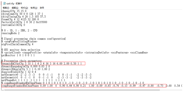
In dynamicCfarConfig setting:
Is the product of the azimuth size and elevation size being used as the fft2DSize?
If so, could this cause discontinuities in the signal and potentially affect detection performance?

Thank you for your assistance.

Henry Lin

  • Hi, Henry:

    The phase calibration may not be officially supported in the in-cabin demo.  

    We do not support dynamicCfarConfig  CLI in xWRL6844 in-cabin demo.   

    Which demo are we talking here? Can you confirm?

    Best,

    Zigang

  • Hi Zigang:


    The file is located at the following path:
    radar_toolbox_3_20_00_04\tools\visualizers\AWRL6844_Incabin_GUI\src\chirpConfigs6844.

    The first red box corresponds to my question regarding dynamicCfarConfig.

    If antenna calibration is not supported, how can I obtain the coefficients shown in the second red box?

    I have another question: why is the save setting in factoryCalibCfg set to 1?

    Thank you for your reply.

    Henry Lin

  • HI, Henry:

    The azimuth and elevation size is not defined through CLI.  IT is hard coded as 17 * 17 in the range-azimuth-elevation heatmap generation.  The algorithm is not using 2D FFT for angle spectrum generation, instead Capon2D or MVDR method is used. 

    The demo does not support range/phase calibration, you have to use SDK demo for range/phase calibration and apply the result in this demo.

    Best,

    Zigang

  • Hi Zigang:

      I read that the spectrum is calculated using Capon beamforming.
    My question is: at this range, when processing the 2D (nu-mu) spectrum through the CFAR module, is it treated as 1D input data for the detection algorithm?
    If so, could this cause discontinuities in the spectrum that might affect detection?
    Additionally, can the factoryCalibCfg save setting help to confirm this?

    Thank you for your reply.

    Henry Lin