


Tool/software:
Dear TI Team,
We have built a custom board out of IWR6843AOP. But we are facing issues with uploading the user-application/firmware into the IWR6843AOP.
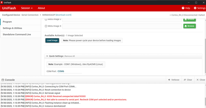
ERROR:
[9/30/2025, 1:13:39 PM] [ERROR] Cortex_R4_0: XXXX Received unexpected data!!!XXXX
[9/30/2025, 1:13:39 PM] [ERROR] Cortex_R4_0: Not able to connect to serial port. Recheck COM port selected and/or permissions.
Important/Relevant Circuit
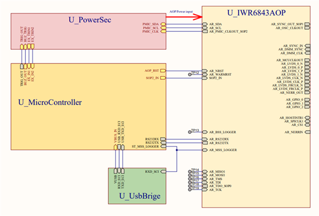
1. Block Diagram
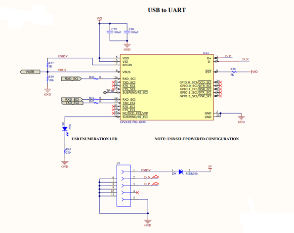
2. USB-TO-UART
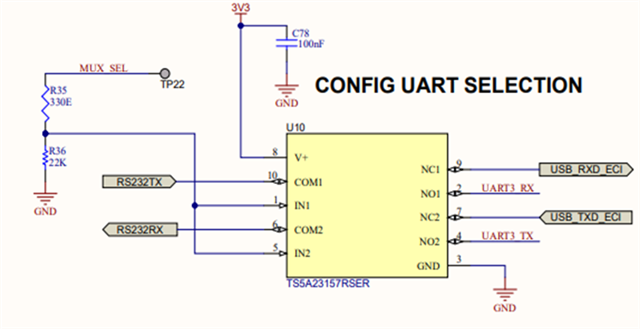
3. UART SELECTION MUX
MUX_SEL: CONTROLLED FROM STM32
|
MUX_SEL |
OUTPUT |
|
0 |
RS232TX, RS232TX of IWR routes to CP2105 and then finally to USB |
|
1 |
RS232TX, RS232RX of IWR routes to STM32UART |
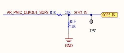
4. SOP [2]
SOP2_IN -> SIGNAL FROM STM32
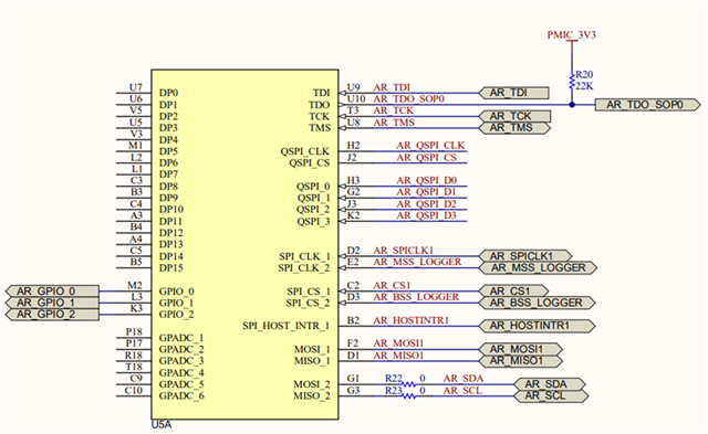
5. SOP [1]: Always tied to 0
6. SOP [0]: Always tied to VCC
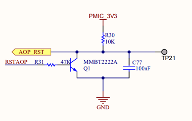
7. IWR6843AOP RESET CIRCUIT
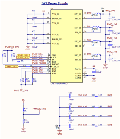
8. PMIC
OBSERVATION TABLE
|
S.NO |
OBSERVATION / REMARKS |
|
1 |
2 COM PORTS ARE BEING SHOWN IN DEVICE MANAGER (Standard & Enhanced) |
|
2 |
VIN_B0, B1, B2, B3 of PMIC is 4.77V |
|
3 |
PMICVIO_3V3 is 3.08V |
|
4 |
PMIC_3V3 = 3.3V |
|
5 |
PMIC_1V2 = 1.2V |
|
6 |
PMIC_1V0 = 1V |
|
7 |
PMIC_1V8 = 1.8V |
|
8 |
VOUT_PA_SUPPLY / AR_1P0_RF2 = 1V |
|
9 |
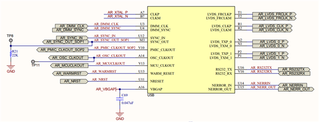
AR_1V4_SYNTH = 0V |
|
10 |
AR_1V4_APLL = 1.36V |
|
11 |
SOP [2:1:0] = 101 (For flashing mode) SOP2: 3.1V (In original schematic R18 was 22K, Changed it on the board to 1K) SOP1: 0V SOP0: 3.32V |
|
12 |
AR_VBGAP = 0.88V |
|
13 |
AR_WARMRST (It is always low …. I am not able to see logic 1-> 0 at nRESET 0->1 on my oscilloscope Moreover, in the reference design of the EVK. It is pulled up to 3.3V. |
|
14 |
AR_NRST = AOP_RST = 3.21V |
|
15 |
MUX_SEL = 0V |
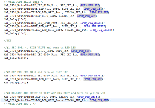
To ensure there is no race condition and SOP2 value (controlled by STM) stabilizes before AOP is booted. We again pull AOP_RST to low for some time after SOP is stabilised using the below code
Any help regarding the above situation will be highly appreciated.
Thanks & Regards
Gagandip Singh Dadhwal
