AWR2944EVM: Synchronize AWR2944EVM’s frame count (,as streamed per TLV), with DCA1000’s

Part Number: AWR2944EVM
Other Parts Discussed in Thread: DCA1000EVM

Hello TI engineers,

I have modified the AWR2944EVM’s HECR demo to stream some custom data via TLV to the host. During this, I need to gather raw ADC data for which I use the DCA1000. These data need to be synchronized, meaning I need to know that frame X from the TLVs, corresponds to frame Y from the DCA.

The way I try to synchronize them now is that I set the DCA and the TLV parser/logger up to listen for data and then I start the AWR from CCS.

However this method is not ideal as the parser can skip some TLVs etc. That’s why I have some questions concerning this:

  • Is there an out of the box way to synchronize both of these streams – for example by embedding into the DCA’s stream the device’s frame number which is streamed in the TLV header?
  • Will the DCA stream/parse all frames, or it too can discard a given frame?

Thanks for your help!

Best regards,

Mark

  • Hi Mark,

    Is there an out of the box way to synchronize both of these streams – for example by embedding into the DCA’s stream the device’s frame number which is streamed in the TLV header?

    Even by enabling CP (Chirp Parameters) data along with ADC data, you will not be able to get frame number. I only see LVDS SW streaming as an option to send custom data.

    Will the DCA stream/parse all frames, or it too can discard a given frame?

    As per the tests that I have performed, you will get all the frames. The only behavior that I have observed is that sometimes, ADC data has 0s. Note: I haven't performed long run tests using DCA1000.

    However this method is not ideal as the parser can skip some TLVs etc.

    Can you be more precise about this? If you are observing any data drop, you can skip the whole frame's object data. 

    Regards,

    Samhitha

  • Hello Samitha, 

    thank you for your reply. 

    CP (Chirp Parameters) data along with ADC data

    Can you please clarify what do you mean by "chirp parameters along with ADC data"? Do you mean that I could stream these parameters over LVDS via the DCA? 

    Can you be more precise about this?

    I am streaming data simultaneously via UART as TLVs and via the DCA over LVDS. For a given run this results in 2 data files, the raw .bin file and a custom .log file containing the raw log of the TLV data. The TLV data contain the frame number which are embedded into the TLV's header. This frame number is written by the embedded code and so a discarded TLV won't distort the counter.

    My assumption is that if the DCA1000 loges every frame, which as you say it seemingly does - even if the data are corrupted it writes 0's, so the data technically are there for this frame. Then if I start the DCA1000EVM at the same time as I do the TLV logger, then frame X on the captured .bin file via the DCA1000 will correspond to frame X as read form the TLV headers, even if some TLVs were discarded. 

    I hope that you know understand my concern and reasoning, if yes then hopefully you can advise me on whether it is correct! 

    Best regards,

    Mark

  • Hi Mark,

    Can you please clarify what do you mean by "chirp parameters along with ADC data"? Do you mean that I could stream these parameters over LVDS via the DCA? 

    CP data has information about chirp number, profile number etc. You can refer to chapter 10 Chirp Parameters (CP) and Chirp Quality
    (CQ) data of "C:\ti\mmwave_mcuplus_sdk_04_07_01_04\mmwave_dfp_02_04_18_01\docs\mmWave-Radar-Interface-Control.pdf" for the format of CP data. I don't think transmitting of CP data is required in your scenario.

    I hope that you know understand my concern and reasoning, if yes then hopefully you can advise me on whether it is correct! 

    Yes, it's correct. 

    Regards,

    Samhitha

  • Hello Samhitha

    thank you for your reply. 

    I don't think transmitting of CP data is required in your scenario.

    I agree, but since I have got you here already, is CP data streaming over LVDS implemented/tested by default in the HECR demo for the AWR2944EVM?

    One more question concerning LVDS data speed transfer. The documentation provides this equation:

    "Tc * n * B / 8 >= round-up(numAdcSamples * numRxChannels * 4 + 52, 256)"

     With " n-lane LVDS with each lane at a maximum of B Mbps", what is the data transfer rate B by default in HECR demo? 

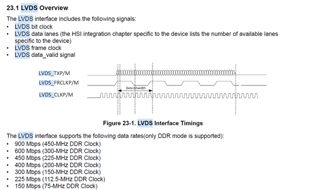
    In the TRM it lists the possible data rates: 

    On the other hand the chirp_design_HECR.h file under the section CSI2 configuration specifies HECR_DATA_RATE as 1U, which is commented as 600Mbps, is this the LVDS data rate, i.e. B?

    Best regards, 

    Mark