DRV421EVM: Core slot influence

Part Number: DRV421EVM
Other Parts Discussed in Thread: DRV421

Hi Team,

Posting on behalf of our customer.

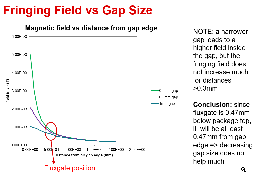
My question arises from designing the core and introducing an air gap. When adding an air gap the inductance of the secondairy winding drops and the Gain of the core (Gcore = B/Ip) also drops consequently dropping the Gmod value to select.

My question is: Does adding the slot to the core have the same effect as adding more air gap to the core?

Because if it does, I need to increase the total air gap value in my calculations to deside the other parameters of the core including the amount of secondairy windings.

Furthermore, I only want to measure DC current with a single primairy wire passing through the core.

When using the calculation sheet that comes with the chip my design falls into the Gmod [10] setting (as the DRV421EVM defualt setting) however, this is without the consideration of the slot gap.

Regards,

Danilo

  • Hello Danilo,

    My question is: Does adding the slot to the core have the same effect as adding more air gap to the core?

    By slot do you mean similar to the drawing here?  Core specifications for DRV421 

    If so this will change the inductance slightly but not as much as the air gap.  This post has some files you can use to simulate both.  DRV421: Question about use case condition 

    Regards,

    Javier

  • Hi Javier,

    Thank you very much for these information.

    Regards,

    Danilo

  • Hi,

    I am the customer who Danilo referred to in the main question.

    Yes, this is indeed the slot that I am talking about. Thank you for your awnser, tho your awnser made me come up with a new question that came from the post you mentioned in the reply.

    -"3) The smaller the air gap the better the magnetic gain and external noise rejection. But there are diminishing returns after about between 0.1mm to 0.3mm because the sensor inside the DRV421 is 0.4mm inside the package and the sensor cannot get any closer to the air gap." ~ Patrick Simmons

    What does the quote mean?

    I understand it as, the gap of the core (not talking about the slot for the sensor) cannot be bigger than 0.3mm as is puts the sensor in diminishing returns.

    With kind regards,

    Emanuel

  • Hello Emanuel,

    Here is a plot that shows the gain with smaller air gap is large as you get closer to the air gap.  You see that even though you have larger gain with smaller air gap at the sensing location you will have less gain as you mover further away from the air gap.  The limit is the sensor location in the package as you cannot get the sensor closer than 0.47mm.  All this can be simulated using FEMM.  The Script I have written and can be downloaded can be used to verify all these are the files I would use.  The PPTX shows how to use FEMM with the script. 

    /cfs-file/__key/communityserver-discussions-components-files/1023/8037.Build_5F00_Magnetic_5F00_Core.lua

    /cfs-file/__key/communityserver-discussions-components-files/1023/4118.Build_5F00_Magnetic_5F00_Core_5F00_NoCutout.lua

    /cfs-file/__key/communityserver-discussions-components-files/1023/5224.Magnetic-Cores-No-Cutout-with-FEMM-and-LUA.pptx

  • Hi Javier,

    Thank you for your response, this helps a lot.

    I no longer have questions for now.

    With kind regards,

    Emanuel

  • Hello Javier,

    After reading a bit more in the datasheet, I find that the fluxgate sensor saturates at 1.7mT.

    My question is, does the calculator made my Texas Instruments take this into accountability?

    Because with my configuration, the calculator shows 0 errors or warnings, but at the current that i want to measure, my calculation indicates a magnetic field strength of 22mT.

    My test set up for the DRV421EVM is as follows:

    Outer diameter 0.094 m

    Inner diameter 0.062 m

    Gap length 0.001 m

    Relative permeability 2000

    Secondary windings 800

    Primary windings 1

    Cable diameter 0.25 mm (which results in a total resistance of 37.7415 ohm)

    I then get a 0.489 H inductance

    A Gcore of 1119 uT/A

    and a Gmod of 1.83

    The shunt value is as the EVM board offers... 10 ohms

    Based on my calculations @ 20 A I have a B of 0.02238T which is > 1.7mT

    Kind regards

    Emanuel

  • Emaneul,

    This is a feedback network where the DRV421 will drive the compensation coil to make the field at the sensor equal to zero.  You can think of it as a feedback network of an amplifier.  This brings the field to zero similar to that of an amplifier.  

    G core gain is 1119µT/A but this is not the gain at our device.  If you use the FEMM tool you can see this and this is described in the prestation.  I did not have your thickness so I simulated a smaller inductance than you did.

    Magnetic Cores designs with FEMM.pptx

    Regards,

    Javier

  • Hie Javier,

    I forgot to mention the height of my core indeed, it is 0.04 m

    Thanks for the reply but this does not answer my question yet. As i understand, the sensor measures the magnetic field generated by the primary conductor. Based on the strength of this magnetic field, the chip sends a compensation current through the compensation winding. If the strength of the magnetic field caused by the PRIMARY winding surpasses 1.7mT, the DRV will go into saturation and error mode (that is how I understand the working principle of the chip). Which formula are you using to calculate B to determine how much the DRV is sensing? I am using the following formula. (whether you use the primary current with the primary winding or the secondary current with the secondary winding doesnt matter as it is a ratio which always generates the same value for I * N.

    My main question is, how do I calculate how much Tesla the fluxgate chip is sensing, to prevent the fluxgate from saturating?

    Np = primary winding

    Ip = Primary current

    Rmc = Reluctance of the core

    Rmg = Reluctance of the gap

    A = cross section of the core

    Kind regards,

    Emanuel

  • Hello Emanuel,

    Thanks for the reply but this does not answer my question yet. As i understand, the sensor measures the magnetic field generated by the primary conductor. Based on the strength of this magnetic field, the chip sends a compensation current through the compensation winding. If the strength of the magnetic field caused by the PRIMARY winding surpasses 1.7mT, the DRV will go into saturation and error mode (that is how I understand the working principle of the chip).

    This is not how it works.  The compensation current through the windings brings the field at the sensor back to zero.  For example with easy numbers.  I have 1200 turns on the compensation windings and I have 10A through the primary.  When the DRV421 is sensing the field it generates a compensation current of 10A/1200 = 8.33mA.  This current is in the opposite direction of the primary current causing the field to be canceled at the DRV421 sensing element.  Then you use the Rshunt to measure your 8.33mA to calculate your primary current. 

    It normally saturates if your reach your current limit on the compensation coil and cannot compensate for the primary or your compensation is connected in a positive feedback loop which you can simply reverse the connection on your compensation coil.

    Regards,

    Javier

  • Thank you Javier for your reply.

    The chip has the pins OR and ER as open drain active low. I'm trying to indicate the status of these pins with an LED. I am reading a lot about possibly damaging the pin due to high current. I have also seen this circuit coming around.

    My question is, what maximum current does the ER and OR pin allow? As these values are not shown in the datasheet, is a NPN transistor used for the ER and OR pins?

    Kind regards,

    Emanuel

  • Hello Emanuel,

    Normally these are specified with an output votlage at a specific current level.  So after some amount of current the resistance of the internal FET that is diving in low will not be able to provide the current.  I would not go over 25mA but recall the votlage drop will increase and may not give you the output low voltage desired once there is more current.  Depending on the LED current requirements you could drive it from 5V to resistor to LED.

    Regards,

    Javier

  • Thank you for your reply Javier,

    I just tested the DRV421EVM and noticed something interesting. When turning on the chip the DEGAUS happens and then a certain internal offset is displayed on the ADC. I noticed that the scale of the offset is incredibly sensitive to the orientation of the chip in the core slot. If the chip is tilted slightly inside the slot the offset is larger (around 14 mV). I noticed that when I get the chip as perpendicular as possible to the core inside the slot the offset is at the 2 mV range. Is it better to create a slot that perfectly fits the sensor? Or should i leave some space between the chip and the core and how much?

    Kind regards,

    Emanuel

  • Hell Emanuel,

    Moving the DRV421 away from the air gap or moving the angle will decrease the magnetic core gain.  Below is an example of the error when you change the magnetic gain.

    You can use DRV421 in our system calculator and see your core has a magnetic gain of 500uT/A and an offset of 8uT for the DRV421 we get an offset of 16mA. 

    8µT/(500µT/A) = 16mA (Primary current error)
    This they calculates as 16mA/1000 = 16µA on compensation coil

    Regards,

    Javier

  • Hi Javier,

    Thanks for your reply.

    Though I am getting an offset in mV not mA, because I am measuring on Vout and Refout. How can I use the values you gave to calculate the total offset in Volts?

    With kind regards,

    Emanuel

  • Hi Emanuel,

    Javier is out of office, but will reply when he returns on 11/6/2025. Thank you for your patience.