


1. Problem Description
Recently, the production team has reported 3 cases of a fault where the key backlight of the display remains constantly on when powered on after aging. The display resumes normal operation after a power-off and restart; however, if the display is left unused for a period of time and then powered on again, there is a chance that the key backlight will stay on constantly once more.
2. Analysis
2.1 Working Principle
The software on the main board of the CPU configures the parameters of the OPT3001 via the I2C bus, reads the ambient light sensor data, and transmits a protocol to the main key board to turn the key backlight on or off based on the set ambient light intensity threshold, thereby controlling the on/off state of the key backlight.
Under normal circumstances, the key backlight turns on when the sensor is blocked; when light of a certain intensity irradiates the sensor, the key backlight turns off. The block diagram of the working principle is shown in Figure 1.

Figure 1
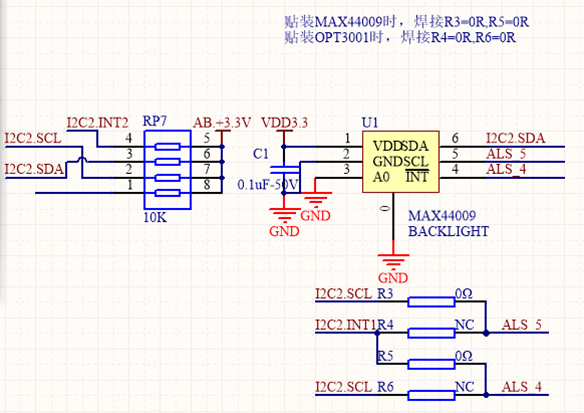
SCH
As can be seen from the schematic diagram, the device we use adopts a compatible design for two types of components. In actual production, the OPT3001 is utilized, which is connected to the corresponding pins of the CPU via an I2C bus and equipped with a 10K pull-up resistor. The CPU of the display terminal periodically configures and detects the registers of the OPT3001 to collect the ambient light value. When the ambient light is lower than the threshold, the CPU turns on the key backlight.
During the debugging process, some individual display terminals exhibit the phenomenon of constant key backlight illumination when powered on and started. The fault disappears upon re-powering; however, if the terminal is powered off and left unused for several hours, the fault will reoccur when the power is turned on again.
When the fault occurs, the I2C signal is measured, and the waveform obtained is as shown Figure 2.

Figure 2
The OPT3001 does not respond to the input signal, making it impossible for the application program to read valid data.
2.2 Overall Machine Measurement
When the backlight remains on abnormally, the test program fails to read the light sensor data, as shown in Figure 3:
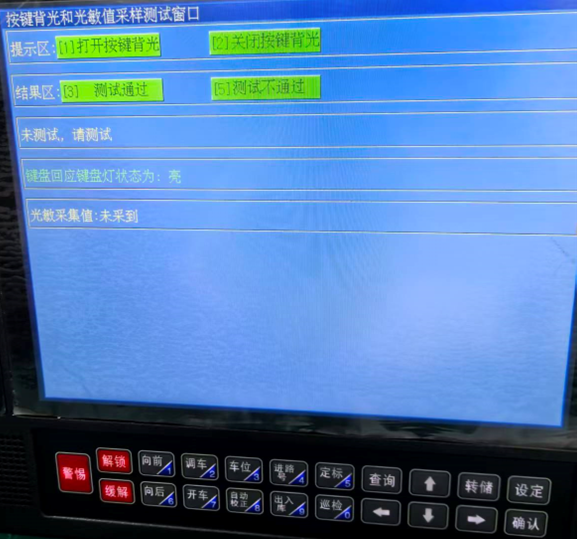
Figure 3: Abnormal Backlight Constant On When Light Sensor Malfunctions
2.3 Power Supply and Waveform Measurement
Tests were conducted when the key backlight was on abnormally. Measurements showed that the CPU power supply and the light sensor power supply were normal; however, the software received no response when reconfiguring or reading data from the light sensor chip. After turning off the 3.3V power supply and turning it on again, the key backlight returned to normal. The measured abnormal waveform is shown in Figure 3. In contrast, under normal conditions, the light sensor chip responds properly to configuration and data reading commands, and the normal waveform is shown in Figure 4:

Figure 4: Abnormal Waveform
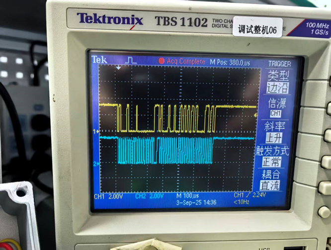
Figure 5:Normal Waveform
2.4 Chip Soldering Inspection
The soldering process of the light sensor (OPT3001DNPRQ1) was inspected, and no abnormalities were found. The reflow oven temperature profile was normal, with no obvious damage to the chip appearance, no internal wire breakage, and good soldering of the chip bottom and pins confirmed via X-ray inspection.

Electronic Magnifier Observation Image
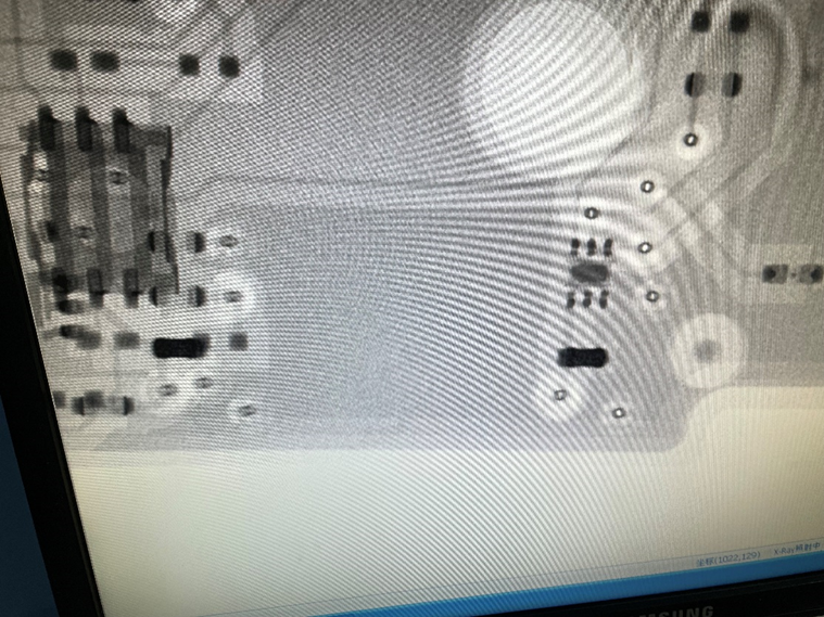
X-ray Inspection Image of Pin and Bottom Soldering
3. Analysis Conclusion
Based on the above analysis, it is initially inferred that the fault is caused by the light sensor chip itself—there is a phenomenon where the chip fails to work upon the first power-on after long-term storage.
