


Dear TI Support Team,
I am currently testing the Long Range People Detection project using the IWR6843ISK board.
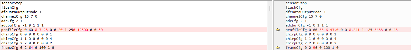
When I import the following CFG file into the “mmWave Industrial Visualizer.exe”, the board successfully transmits the Point Cloud data to the GUI.
sensorStop
flushCfg
dfeDataOutputMode 1
channelCfg 15 7 0
adcCfg 2 1
adcbufCfg -1 0 1 1 1
profileCfg 0 60 35 6 43.0 0 0 8.241 1 125 3433 0 0 48
chirpCfg 0 0 0 0 0 0 0 1
chirpCfg 1 1 0 0 0 0 0 4
chirpCfg 2 2 0 0 0 0 0 2
frameCfg 0 2 96 0 100 1 0
lowPower 0 0
guiMonitor -1 1 0 0 0 0 0
cfarCfg -1 0 2 8 4 4 0 10 0
cfarCfg -1 1 0 4 2 3 1 10 0
multiObjBeamForming -1 1 0.5
clutterRemoval -1 1
calibDcRangeSig -1 0 -5 8 256
extendedMaxVelocity -1 0
bpmCfg -1 0 0 1
lvdsStreamCfg -1 0 0 0
compRangeBiasAndRxChanPhase 0.0 1 0 1 0 1 0 1 0 1 0 1 0 1 0 1 0 1 0 1 0 1 0 1 0
measureRangeBiasAndRxChanPhase 0 1.5 0.2
CQRxSatMonitor 0 3 4 63 0
CQSigImgMonitor 0 127 4
analogMonitor 0 0
aoaFovCfg -1 -90 90 -90 90
cfarFovCfg -1 0 0 59.99
cfarFovCfg -1 1 -30 30.00
staticBoundaryBox -50 50 0.5 60 -0.5 6
boundaryBox -50 50 0.5 60 -0.5 6
sensorPosition 2 0 0
gatingParam 4 6 6 6 10
stateParam 4 10 60 600 20 600
allocationParam 30 30 0.5 3 2 2
maxAcceleration 0.1 0.1 0.1
trackingCfg 1 2 250 20 78 121 99
presenceBoundaryBox -3 3 2 6 0.5 2.5
sensorStart
However, when I import the modified CFG file shown below, the GUI does not receive any Point Cloud data from the board.
sensorStop
flushCfg
dfeDataOutputMode 1
channelCfg 15 7 0
adcCfg 2 1
adcbufCfg -1 0 1 1 1
profileCfg 0 60 8 7 28 0 0 20 1 256 12500 0 0 30
chirpCfg 0 0 0 0 0 0 0 1
chirpCfg 1 1 0 0 0 0 0 4
chirpCfg 2 2 0 0 0 0 0 2
frameCfg 0 2 64 0 100 1 0
lowPower 0 0
guiMonitor -1 1 0 0 0 0 0
cfarCfg -1 0 2 8 4 4 0 10 0
cfarCfg -1 1 0 4 2 3 1 10 0
multiObjBeamForming -1 1 0.5
clutterRemoval -1 1
calibDcRangeSig -1 0 -5 8 256
extendedMaxVelocity -1 0
bpmCfg -1 0 0 1
lvdsStreamCfg -1 0 0 0
compRangeBiasAndRxChanPhase 0.0 1 0 1 0 1 0 1 0 1 0 1 0 1 0 1 0 1 0 1 0 1 0 1 0
measureRangeBiasAndRxChanPhase 0 1.5 0.2
CQRxSatMonitor 0 3 4 63 0
CQSigImgMonitor 0 127 4
analogMonitor 0 0
aoaFovCfg -1 -90 90 -90 90
cfarFovCfg -1 0 0 59.99
cfarFovCfg -1 1 -30 30.00
staticBoundaryBox -50 50 0.5 60 -0.5 6
boundaryBox -50 50 0.5 60 -0.5 6
sensorPosition 2 0 0
gatingParam 4 6 6 6 10
stateParam 4 10 60 600 20 600
allocationParam 30 30 0.5 3 2 2
maxAcceleration 0.1 0.1 0.1
trackingCfg 1 2 250 20 78 121 99
presenceBoundaryBox -3 3 2 6 0.5 2.5
sensorStart
The only changes I made are highlighted in the image below.
Could you please review why this configuration does not work properly,
even though the rest of the parameters remain the same structure?
Thank you for your assistance.
Best regards,
Jaehoon Kim

