This thread has been locked.

If you have a related question, please click the "Ask a related question" button in the top right corner. The newly created question will be automatically linked to this question.

DRV5055: Regarding sensor calibration and software

Part Number: DRV5055
Other Parts Discussed in Thread: TMAG3001EVM, TMAG3001

Hi Team,

Posting on behalf of our customer.

We are using the DRV5055A1ELPGQ1 Hall sensor to detect a magnetic field. In our system, we use ring magnets, and by arranging multiple ring magnets together, they are expected to behave like a single magnet.

When the effective magnet length is around 60 mm, the magnets behave like a single magnet and the Hall sensor output is stable. However, when the magnet length is increased up to 200 mm, the magnets no longer behave like a single magnet, and the Hall sensor output becomes non-uniform.

We are using ring magnets of different sizes: 3 mm, 6 mm, 20 mm, and 28 mm. We tried with all size of magntes it is giving non uniform values only.The Hall sensor output is read using a 12-bit ADC in an STM32 controller.

For your reference, we have attached the Hall sensor output ADC Readings. Please suggest a solution to resolve this issue and also suggest some better resolution hall sensor are available.

ADC.xlsx 

Regards,

Danilo

  • Hi Danilo,

    Our experts on this topic are currently out of office for the holidays.  They should be able to respond after they are back on January 5th.

    Regards,

    Mekre

  • Hi Danilo,

    Thank you for posting to the Sensors forum!

    Are you able to share a diagram of the magnet being used both for when the magnet length is 60mm and when it is 200mm. Also what type of magnet is being used: neodymium, rubber, etc. What is the strength of the magnet? Additionally, how is the sensor being placed with respect to the magnet?

    Best,

    ~Alicia

  • Hi Alica,
    Type : Ring magnet
    Magnetisation : Axial
    Grade :N45
    Strength :N45 grade
    Dimensions : 6*3*28mm
    For your refrence i had attched the hall sensor position image and the 60mm and 200mm magnet length.

  • Hi Hariprasath,

    Regarding movement, is it the magnet that moves, or the sensor? If so, how is it moving?

    Are you able to provide more specific positioning information of the sensor with relation to the magnet? I would like to run a simulation to try and see what the expected magnetic field would look like for the 200mm length.

    Best,

    ~Alicia

  • Hi Alica,

    The Hall sensor board is fixed, and the magnetic stack moves up and down. Based on this movement, we obtain the ADC values from the Hall sensor.

    Please let me know if you have any queries.

    Best regards,
    Hariprasath

  • Hi Alica,

    6661.ADC.xlsx
    For your reference ADC Values table are attched.

  • Hi Hariprasath,

    Sorry, I forgot to ask but, how many poles do the axially split ring magnets have?

    For the actual magnet detection, are you just looking for positive to negative transitions? If so, would a hall switch/latch work for your application? Or do you specifically need the ADC output?

    Best,

    ~Alicia

  • Hi Alicia,

    An axially magnetized ring magnet has two poles only: one North pole on one flat face and one South pole on the opposite flat face. When multiple ring magnets are combined and aligned in the same orientation, they act as a single magnet with the same two poles (North and South).

    For magnet detection, we are looking for positive-to-negative magnetic field transitions. As the magnet stack moves past a fixed Hall sensor, the sensor output:

    1. Increases with the magnetic field

    2. Crosses the center point (zero or mid-scale)

    3. Decreases as the field moves away

    Regarding the output type, yes, we specifically require an ADC output. A linear Hall-effect sensor with analog output is needed, which provides:

    1. A linear, ratiometric output (approximately Vcc/2 at zero magnetic field)

    2. A smooth voltage change proportional to the magnetic field strength

  • Hi Hariprasath,

    Thank you for the additional information!

    Would you be able to share the specific distance measurement from the sensor to the magnet? This will help with the simulation that I am trying to run.

    Best,

    ~Alicia

  • Hi Alicia,

    The distance between the Hall sensor and the magnet is maintained in the range of 1 mm to 1.5 mm.

    Best regards,
    Hariprasath

  • Hi Hariprasath,

    Thank you for clarifying!

    I should be able to have some preliminary results to share on Monday from a TIMSS simulation that I can share with you then so that we can compare the results.

    Best,

    ~Alicia

  • Hello Alicia,

    Is there any upadate regarding the preliminary results?

    Best,
    Hariprasath K

  • Hi Hariprasath,

    Thank you for your patience and apologies for the delayed response!

    I was able to complete the preliminary simulation. As when stacked on top of each other, the axially split magnet should just act as 1 long magnet, I ran the simulation with just one magnet as TIMSS currently only supports 1 magnet. 

    I've included a screenshot of the results below. For the simulation, I used the DRV5055A2QLPG as this variant was able to better capture the full magnetic range of the magnet's movement without saturating. 

    When capturing your data, is the magnet being moved by hand? If so, it could be possible that the noise seen as the magnet's center moves over the sensor is the result of shaky movement. Another potential cause is that something nearby (some metal object/component) could be affecting the results being observed.

    Best,

    ~Alicia

  • Thanks for the reply, Alicia.

    I reviewed the preliminary results shown in the images you shared. I understand that the tests were performed using a single magnet; however, our requirement is to combine multiple magnets so that they behave as a single continuous magnet.

    From my understanding of your results with the 200 mm magnet, the first 30 mm and the last 30 mm show a measurable magnetic field, while the region in between shows nearly zero magnetic field. Our expectation is different: we want the magnetic field to be distributed across the entire magnetic stack.

    Ideally, the magnetic field should vary continuously along the length of the stack—for example, starting around 3.3 V at the south pole and gradually transitioning to about 0.2 V at the north pole. The intermediate region should also exhibit a measurable magnetic field, rather than dropping to same magnetic field.

    Could you please suggest how we might achieve this behavior using combined magnets?

    Best,
    Hariprasath K

  • Hi Hariprasath,

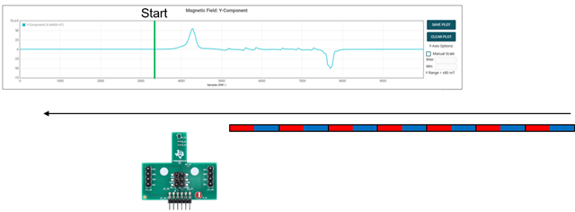
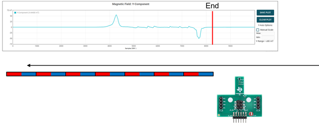
    I was able to use a TMAG3001EVM that I had on hand with 7 stacked axially split cylindrical magnets (1/8in x 1in N42) to observe what the magnetic field would look like as the magnets moved by. I started with the stack of magnets held a bit away from the EVM (see image below on the left for start position) and moved the stack of magnets over the device until the stack of magnets had fully passed over the EVM (see image below on the right for end position).

    From the above images, as the magnets initially approached, the magnetic field increases before falling back down to 0 until it reaches the last magnet, similar to the results of the TIMSS simulation of the 1 long magnet.  

    If wanting to use combined magnets, one option that I can think of is using diametrically split ring magnets and stacking those on top of each other. To keep track of where along the magnet you are, you will need to keep a count of how many times the polarity of the magnets change. With this option, the magnetic field/device output would look something similar to the below:

    For the above I used muti-pole bar magnet to get an idea of of what the magnetic field would roughly look like with stacked diametrically split ring magnets.

    Best

    ~Alicia

  • Thanks for the reply, Alicia.
    I just want to know which simulation tool you using to test this environment.If i know that simulation tool it will be useful to understand more from my side.I know the TIMSS tool.But this looks different from TIMSS tool.Please share the details of this simulation tool.

    Best Rgards,
    Hariprasath K.

  • Hi Hariprasath,

    This actually wasn't a simulation tool. This was tested out with our TMAG3001EVM (which uses a 3D sensor) and the TMAG3001EVM GUI. I used the TMAG3001EMV GUI as it allowed for me to plot the magnetic field read by the TMAG3001 as I moved the stacked cylindrical magnets over the sensor to help get an idea of what the Bx and By magnetic field would look like.

    Best,

    ~Alicia

  • Hi Alicia,

    I ran a simulation for the 85 mm magnet using TIMSS. In the results, the mid-range values appear almost the same, with only minute variations. After the third decimal place, I can see slight changes, but I’m not sure whether the sensor will be able to capture such small differences.

    Could you please suggest any ways to obtain more noticeable variation in the values?

    For reference, I have attached the simulation results from TIMSS.85mm_magnet.pdf

    Best regards,
    Hariprasath K

  • Hi Hariprasath,

    The best way to do this would be to use diametrically split cylindrical/ring magnets or stacked bar magnets similar to the simulation attached below.

    {
      "version": "3.5.0",
      "design_name": "StackedBarMagnetExample",
      "magnet_id": 1,
      "poles": 28,
      "material_id": 1,
      "grade_id": 1,
      "select_remanence": "br_average",
      "remanence": 1200,
      "temperature": 20,
      "temperature_coefficient": -0.12,
      "coercivity": 10.9,
      "function_id": 2,
      "magnet_geometry": {
        "magnet_length_x_dim": 85,
        "magnet_length_y_dim": 4,
        "magnet_length_z_dim": 4
      },
      "magnet_position": {
        "x_position": 0,
        "y_position": 0,
        "z_position": -41
      },
      "magnet_angle": {
        "x_angle": 0,
        "y_angle": 90,
        "z_angle": 0
      },
      "magnet_movement": {
        "final_x_position": 0,
        "final_y_position": 0,
        "final_z_position": 41
      },
      "sim_setting": {
        "step_size": 0.25
      },
      "sensor": [
        {
          "sensor_id": "DRV5055",
          "sensor_position": {
            "x_position": 7,
            "y_position": 0,
            "z_position": -1.61
          },
          "sensor_angle": {
            "x_angle": 0,
            "y_angle": 0,
            "z_angle": 90
          },
          "custom_inputs": {
            "variant": "DRV5055A2QLPG",
            "applied_vcc": 3.3
          },
          "id": 33846,
          "user_design": 47914
        }
      ]
    }

    With the above stacked bar magnet, you are able to get varying values, you would just need to keep track of the negative to positive field transitions.

    Best,

    ~Alicia