This thread has been locked.

If you have a related question, please click the "Ask a related question" button in the top right corner. The newly created question will be automatically linked to this question.

MMWAVE-L-SDK: AWRL1432: rlexample_perchirplut build error/ usage.

Part Number: MMWAVE-L-SDK
Other Parts Discussed in Thread: SYSCONFIG, AWR2944, AWRL6844, AWRL6432BOOST, AWRL1432

Good afternoon experts, here are the software dependencies: 
 Tools/ software: 
1) ccs 12.8.1 (sysconfig 1.21).
2) MMWAVE_L_SDK_05_05_02_00 (05_05_20_00).
3) AWRL1432-EVM

Reference example: 

1) ti\MMWAVE_L_SDK_05_05_02_00\firmware\mmwave_dfp\examples\source\rlexample_perchirplut.
2) ti\MMWAVE_L_SDK_05_05_02_00\firmware\mmwave_dfp\examples\source\rlexample_coldboot.
3) ti\MMWAVE_L_SDK_05_05_02_00\firmware\mmwave_dfp\examples\source\rlexample_setup.

Questions:  
1) I am trying to use this rlexample_perchirplut example to do multi chirp config within the same frame. But when i try to build it in CCS, i end up getting this build error due to missing header files "C:/ti/MMWAVE_L_SDK_05_05_02_00/firmware/mmwave_dfp\examples/include/rlexample.h:200:11: fatal error: 'platform/xwrlx432/syscore/include/sys_main.h' file not found" 

2) The goal is to be able to configure each chirp C0 with a positive slope and C1 with a negative slope, similar to how profile Cfg 0 and 1 can be assigned in AWR2944. I would like to configure the frame such as C0(+ve slope) C1(-ve slope) C2(+ve slope).... CN ,Is this reference example the best way to go about it or is there any other solution for the same? 

Attempts to understand:

1) https://e2e.ti.com/support/sensors-group/sensors/f/sensors-forum/1368920/awrl1432-awrl1432-waveform-configuration---2-different-chirp-configure-in-a-single-frame/5232467 with reference to this forum, they have suggested the same example i am trying to build.  

2) I have also downloaded older SDKs to check this missing folder but unable to locate it. 

Please feel free to ask for more follow up to help in the debug. Thank you. 

Sincerely, 
Rohith Gopakumar

  • Hi, there:

    The example in firmware folder can be different.  Please give me some time to figure it out.  

    Best,

    Zigang

  • Hello Zigang,

    Thank you for your response. Has there been any updates regarding this question? I have tried the LUT configurations as shown below, could you please have a look and let me know if there is any other consideration to be taken into account to achieve the below configurations?

    Configs: 
    1) Tx = 2.
    2) BPM enabled in both Tx.
    3) 8 chirps.
    4) Slope = 4Mhz/us

    Requirement: 
    Frame0 = | C0(+ve slope), C1(-ve slope), C2(+ve slope), C3(-ve slope), C4(+ve slope), C5(-ve slope), C6(+ve slope), C7(-ve slope) |. This is the requirement. 

    Steps Taken: 
    I have gone though the "MMWAVE_L_SDK_05_05_02_00/firmware/mmwave_dfp/docs/mmwave_dfp_low_api_documentation" to understand how to use the LUT configurations. I have also refered the "rlexample_perchirplut" to understand the flow of the code. The main objective is to be able to create alternating chirps in a frame.

    The below snippets are taken from the mmwave demo example provided and an LUT function has been added to it as shown below. 

    1) Creating the LUT structure 


    2) Filling the LUT and giving paramArrayLen and the start addresses of each of the parameters.


    3) Calling the "rl_sensPerChirpCfg" and "rl_sensPerChirpCtrl" API calls to set the configuration. 


    4) Call this function before mmwave config (This is from the Mmwave demo example) in mmw_cli.c, since in the documentation it is mentioned that if the LUT is enabled, the RF front end takes the chirp config directly from the LUT and any config given through "chirpTimingCfg" is ignored since now config is taken from LUT. 


    Are these configurations enough to get alternating chirps with positive and negative slopes respectively? Is it sufficient for the get APIs to pass to ensure this config has been applied? Could you shed some light on these questions and how to verify successful application. Thank you. 

    Sincerely,
    Rohith Gopakumar

  • Hi, there:

    I have not heard back on the compiling for the examples in firmware directory. 

    I am off for these several days and will get back to you with more information. 

    But I have one question on your configuration below:

    Configs: 
    1) Tx = 2.
    2) BPM enabled in both Tx.
    3) 8 chirps.
    4) Slope = 4Mhz/us

    Requirement: 
    Frame0 = | C0(+ve slope), C1(-ve slope), C2(+ve slope), C3(-ve slope), C4(+ve slope), C5(-ve slope), C6(+ve slope), C7(-ve slope) |. This is the requirement. 

    Can you listing how BPM is enabled for these 8 chirps.  Is C0 with TX1 + TX2, and C1 with TX1 - TX2?

    Best,

    Zigang

  • Hello Zigang,

    Thank you for your response. 

    Is C0 with TX1 + TX2, and C1 with TX1 - TX2?

    This is correct yes. C0 is configured with TX1 + TX2, and C1 is with TX1 - TX2. In the LUT i have given 0x33 for the bpm enable. Are these configurations sufficient to do the requirement? Feel free to ask for follow up questions to help in the debug.

    Sincerely,
    Rohith Gopakumar

  • Hi, there:

    First the BPM per chirp LUT for BPM should have two entry

    chirpCfg.h_ParamArrayLen[M_RL_SENS_PER_CHIRP_BPM_ENABLE] = 2U;
    sensPerChirpLuTable->ChirpBpmEn[0] = 0x0000U;                                            
    sensPerChirpLuTable->ChirpBpmEn[1] = (uint8_t)(CHIRP_TX1_BPM_EN_SEL); 

    Second, when you have two chirps for BPM, I expect the same exact chirp (including the slope) between them, except the 180 phase rotation.  So, I can not see how one chirp can have positive slope and one can have negative slope.

    should you have the 4 chirps in the order of

    CO: TX1 + TX2, +ve slope

    C1: TX1 - TX2, +ve slope

    C2: TX1 + TX2, -ve slope

    C3: TX1 - TX2, -ve slope

    And then this pattern repeats.

    Let me know if my understanding is correct.

    Best,

    Zigang

  • Hello Zigang,

    should you have the 4 chirps in the order of

    CO: TX1 + TX2, +ve slope

    C1: TX1 - TX2, +ve slope

    C2: TX1 + TX2, -ve slope

    C3: TX1 - TX2, -ve slope

    And then this pattern repeats.

    Thank you for the follow up, yes, that is correct, this is fine. Could you let me know the LUT configurations i need to be making to get the above configuration? Could you also let me know how i can verify if the positive and negative slope has actually taken effect other then the rl_sensPerChirpCfg API command? Thank you for your help and response. 

    Sincerely,
    Rohith Gopakumar

  • Hi, there:

    IN AWRL6844 SDK, we have BPM mode and customer can modify the BPM mode setting inside MMWave_configureChirpMimoPat function.  After the modification, the customer need to rebuild the library.     

    However, we just noticed that our AWRLx432 SDK only support standard BPM and TDM.   You will have to figure out yourself using the example you found.

    We have never tried to have positive slope and negative slope before, please let me know what will be the benefit and difference to have them interleave with each other.

    Best,

    Zigang  

  • Hello Zigang,

    I have gone through the demo code in which they have made the h_ChirpTxBpmEnSel as 0 in mmw_cli.c. Why is it set to 0 even when BPM is enabled by using CLI?. 
      
    With reference to the rlexample_perchirplut example, they have kept the bpm enable as follows: 

    From the documentation it is understood that a single LUT here applies to two chirps. So could you explain to me how these 4 chirps are configured with respect to bpm in mind. In my implementation, what if i set the BPM to 0 and retain the rest of the code as it is, so will i get the following chirp pattern?

    sensPerChirpLuTable->ChirpTxEn[0U] = 0x33;      // Tx enable mask
    sensPerChirpLuTable->ChirpBpmEn[0U] = 0x00;  // BPM enable or not


    C0 (+ve slope and ChirpBpmEn = 0)

    C1 (-ve slope and ChirpBpmEn = 0)

    If yes how is this different from my previous implementation which is: 

    sensPerChirpLuTable->ChirpTxEn[0U] = 0x33;      // Tx enable mask
    sensPerChirpLuTable->ChirpBpmEn[0U] = 0x33;  // BPM enable or not

    C0 (+ve slope and ChirpBpmEn = 3)

    C1 (-ve slope and ChirpBpmEn = 3) 

    In this forum you have used the mmwave studio to decide the configurations for the LUT "AWRL6432BOOST: how to change the chirp parameters of Tx1 and Tx2", could you check if these LUT commands work similarly?

    Please shed some light on this bpm setting to try out the positive and negative slope implementation. 

    Sincerely,
    Rohith Gopakumar


  • HI, there:

    You can find the field in the Interface Control Document inside SDK release firmware folder

    C:\ti\MMWAVE_L_SDK_06_00_05_01\mmwave_l_sdk_06_00_05_01\firmware\mmwave_dfp\docs

    It clearly says that this field will be ignored if per-chirp LUT is programmed.   

    Set anything in h_chirpTxBpmEnSel field means every chirp will have the same phase setting, which is true in TDM mode.  However, BPM mode request the users to program the phase differently in different chirp, so per-chirp LUT will be used to achieve that.    You can search for MMWave_configureChirpMimoPat function to check how the per-chirp LUT is programmed for TDM and BPM mode.  

    Hope this is helpful.

    Zigang

  • Hello Zigang, 

    Thank you for your response. 
    With respect to the interface control document of AWRL1432, it is explained below that the ChirpBpmEn is responsible for 2 chirp configuration in this case. So is it correct understanding that ChirpBpmEn[0U] will configure C1,C0 and ChirpBpmEn[1U] will configure C3,C2 as each nibble is for one chirp. 


    I have taken your help into account and made modifications to the logic as follows. Now i am sending 

    C0(+ve) C1(+ve) C2(-ve) C3(-ve) and so on..


    sensPerChirpLuTable->ChirpTxEn[0U] = 0x33; [C1,C0 - TX en tx1 and tx0]
    sensPerChirpLuTable->ChirpTxEn[1U] = 0x33; [C3,C2 - TX en tx1 and tx0]
    sensPerChirpLuTable->ChirpBpmEn[0U] = 0x30; [C1 - BPM en tx1 and tx0, C0 - 0x0]
    sensPerChirpLuTable->ChirpBpmEn[1U] = 0x30; [C3 - BPM en tx1 and tx0, C2 - 0x0]

    I have done this since in the mmwave_l_sdk_06_00_05_01, in the "MMWave_configureChirpMimoPat " function they have as given below, they have enabled only the tx1 in the case where both tx0 and tx1 are enabled. Using this same logic i have done the above changes. 


    Is this logic implementation correct? If so how can i verify if it is actually behaving as intended?

    Sincerely, 
    Rohith Gopakumar

  • HI, there:

    The first portion looks right. 

    The BPM should follow the example logic 

    sensPerChirpLuTable->ChirpTxEn[0U] = 0x3; 
    sensPerChirpLuTable->ChirpTxEn[1U] = 0x3; 
    sensPerChirpLuTable->ChirpBpmEn[0U] = 0x0;  (TX1 + TX2) 
    sensPerChirpLuTable->ChirpBpmEn[1U] = 0x2; [TX1 - TX2)

    For each above field you programed, please program  chirpCfg.h_ParamArrayLen and chirpCtrl.h_PerchirpParamCtrl register.

    Best,

    Zigang

  • Hello Zigang, 

    Thank you for your response and help. The example you have reference in the above reply is with respect to the "MMWAVE_L_SDK_06_01_00_05", where 8 bits are being used per chirp to do the BPM and Tx enable as shown below.


    But in the "MMWAVE_L_SDK_05_05_02_00", half byte/nibble is being used to do the same per chirp as shown below. 

    So 
    sensPerChirpLuTable->ChirpTxEn[0U] = 0x33; 
    sensPerChirpLuTable->ChirpTxEn[1U] = 0x33; 
    sensPerChirpLuTable->ChirpBpmEn[0U] = 0x20;  (TX1 + TX2) 
    sensPerChirpLuTable->ChirpBpmEn[1U] = 0x20; [TX1 - TX2)
    should be the configuration? You have mentioned the same in this forum too "AWRL6432BOOST: how to change the chirp parameters of Tx1 and Tx2". As shown below. 


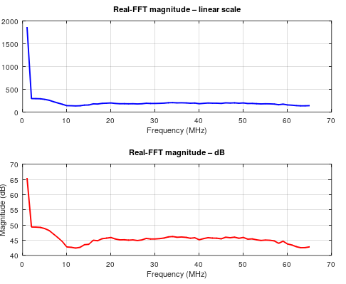
    I have done the collection of ADC data using the EVM board with these modifications made in the mmwave demo code. A strong target was kept at 4m and the range resolution is 0.456. Find the fft and phase plots attached below. 

    Procedure followed: 
    1) Capture the final chirp data sitting in the adc buffer using memory browser as the chirps overwrite in the same location and plot it using matlab to get the fft result. 
    2) First send 1 frame of data with C0(+ve) C1(+ve) C2(-ve) C3(-ve) C4(+ve) C5(+ve) C6(-ve) C7(-ve) to get the negative chirp data sitting in the final buffer output. Then use "save memory" and plot the bin file to get the negative chirp data. 
    3) Repeat this experiment with C0(-ve) C1(-ve) C2(+ve) C3(+ve) C4(-ve) C5(-ve) C6(+ve) C7(+ve) to get the positive slope chirp sitting in the memory browser.
    4) Plot the fft and phase plots found using [plot((imag(fft(adc_real,Nfft))));] of each of the chirps. 

    Case 1: Config - 
    sensPerChirpLuTable->ChirpTxEn[0U] = 0x33; 
    sensPerChirpLuTable->ChirpTxEn[1U] = 0x33; 
    sensPerChirpLuTable->ChirpBpmEn[0U] = 0x20;  (TX1 + TX2) 
    sensPerChirpLuTable->ChirpBpmEn[1U] = 0x20; [TX1 - TX2)

    i) FFT + ve chirp

    Set1

    Set2


    ii) FFT - ve chirp

    Set1:


    Set2:


    iii) Phase plots of both together: 

    Set1: 

    Set2: 


    Case 2: Config (Tried the same config)- 
    sensPerChirpLuTable->ChirpTxEn[0U] = 0x3; 
    sensPerChirpLuTable->ChirpTxEn[1U] = 0x3; 
    sensPerChirpLuTable->ChirpBpmEn[0U] = 0x0;  (TX1 + TX2) 
    sensPerChirpLuTable->ChirpBpmEn[1U] = 0x2; [TX1 - TX2)

    i) FFT + ve chirp


    ii) FFT - ve chirp


    iii) Phase plots of both together:


    Case 3: Config (Modified the config)- 
    sensPerChirpLuTable->ChirpTxEn[0U] = 0x3; 
    sensPerChirpLuTable->ChirpTxEn[1U] = 0x3; 
    sensPerChirpLuTable->ChirpTxEn[2U] = 0x3; 
    sensPerChirpLuTable->ChirpTxEn[3U] = 0x3; 

    sensPerChirpLuTable->ChirpBpmEn[0U] = 0x0;  (TX1 + TX2) 
    sensPerChirpLuTable->ChirpBpmEn[1U] = 0x2; [TX1 - TX2)
    sensPerChirpLuTable->ChirpBpmEn[2U] = 0x0; 
    sensPerChirpLuTable->ChirpBpmEn[3U] = 0x2;

    i) FFT + ve chirp


    ii) FFT - ve chirp


    iii) Phase plots of both together:


    1) These outputs do not seem conclusionary. What i am expecting is that the peak bin of both the negative and positive chirp should have the same magnitude but when we take the phase plot we should have a 180 degree phase shift due to the negative slope.

    2) Why is there an increase in the positive slope noise floor in the set 1 of case 1. And why are the rest of the configurations not even showing a peak in any of them? So does this imply that the understading of the chirp config being done nibble wise is correct? and if so, what is the order of configuration? Is it C1C0 and then C3C2 or the other way around. 

    I hope this information helps, feel free to ask for more clarifications. 

    I have also ensured that the param len is set correctly and have set the repeat count to 1 as shown below.


    Thank you once again for your help and assistance. 

    Sincerely, 
    Rohith Gopakumar


  • Hi, there:

    Here is some examples in firmware directory under SDK release package.

    C:\ti\MMWAVE_L_SDK_05_05_03_00\firmware\mmwave_dfp\examples\source\rlexample_perchirplut.c

    You can follow the procedure.  In terms of verification, I am not familiar with different slope chirp.  But if for BPM, I will apply BPM demodulation first, and then do angle estimation to see whether the angle matches my target angle in the setup. 

    Best,

    Zigang 

  • Hello Zigang, 

    Thank you for your response and help. 

    The example you have given as reference "rlexample_perchirplut.c" shows the same configuration as i have done for the slope and bpm setting. But it dosen't explain why the configuration is being done that way. Could you refer me to some other resource which does the LUT configuration or any other forum which have asked similar questions regarding the LUT configuration.  

    The firmware documentation only mentions the use of the API calls but the peaks of the fft results from the adc data have come out very poor and inconsistent. I have even taken the output by setting the following 

    sensPerChirpLuTable->ChirpTxEn[0U] = 0x33; 
    sensPerChirpLuTable->ChirpTxEn[1U] = 0x33; 
    sensPerChirpLuTable->ChirpBpmEn[0U] = 0x00;  (TX1 + TX2) 
    sensPerChirpLuTable->ChirpBpmEn[1U] = 0x00; (TX1 + TX2)

    I will share the plots for the same if necessary, even this case shows a very negligible peak at the target range. Feel free to ask for more information if it helps in this setup. 

    Thank you once again for your help. 

    Sincerely, 
    Rohith Gopakumar 


  • Hi, there:

    I do not have any other examples.

    Are you placing a strong corner reflector at the bore sight in a clean environment?  Do you see the peak in the range/Doppler FFT output associated with this corner reflector?

    Please can share the plots

    If BPM mode + slope switching does not make sense, can you also check the TDM mode.  You can magnitude square (non-coherently) combined the 2D FFT output from different antennas. 

    Best,

    Zigang

  • Hello Zigang, 

    Thank you for your response. The plots for the range FFT output have come out good. I will attach it below. We can ignore the other peaks due to the testing environment having multi-path reflections.


    Now since the range fft output has come fine, but the individual chirps show the same plots with low amplitude. Upon further analysis, even talking the adc data without the LUT enabled shows the same low amplitude plots. So does this imply that since the range fft output with the LUT is showing a good plot, we can move forward that the +ve and -ve slope have been applied as given by the api? 

    This range fft output is with BPM + slope switching. BPM enable was made as 0X20 for both the positive and negative chirps. 

    Sincerely, 
    Rohith Gopakumar

  • Hi, there:

    I assume this range FFT output plot is in dB, correct? The range FFT data looks good to me.  But you can calculate the Doppler FFT cross chirps off-line.  It will give you better noise floor information.

    Best,

    Zigang   

  • Hello Zigang, 

    Thank you for your response. Yes the range output plot is in dB. Does this conclude that both with and without the LUT addition shows a low amplitude in the ADC plots for a single chirp but when we do the fft across multiple chirps and frames, the range fft output is good since we do the addition accross the chirps. And this is unrelated to the LUT addition? 

    So are we safe to assume that the LUT config changes have taken place? thank you once again for your continued support and help. I will be closing the forum after this reply. 

    Sincerely, 
    Rohith Gopakumar


  • Hi, there:

    The range FFT data looks good to me.  It can also indicate the TX is enabled every chirp.  But again, you will need to go through the angle estimated step to fully convince that the TX/RX channel and BPM phase are programmed correctly.

    Best,

    Zigang