This thread has been locked.

If you have a related question, please click the "Ask a related question" button in the top right corner. The newly created question will be automatically linked to this question.

TMCS1101: application issue.

Expert 2300 points

Part Number: TMCS1101
Other Parts Discussed in Thread: TMCS1123

Hi Team,

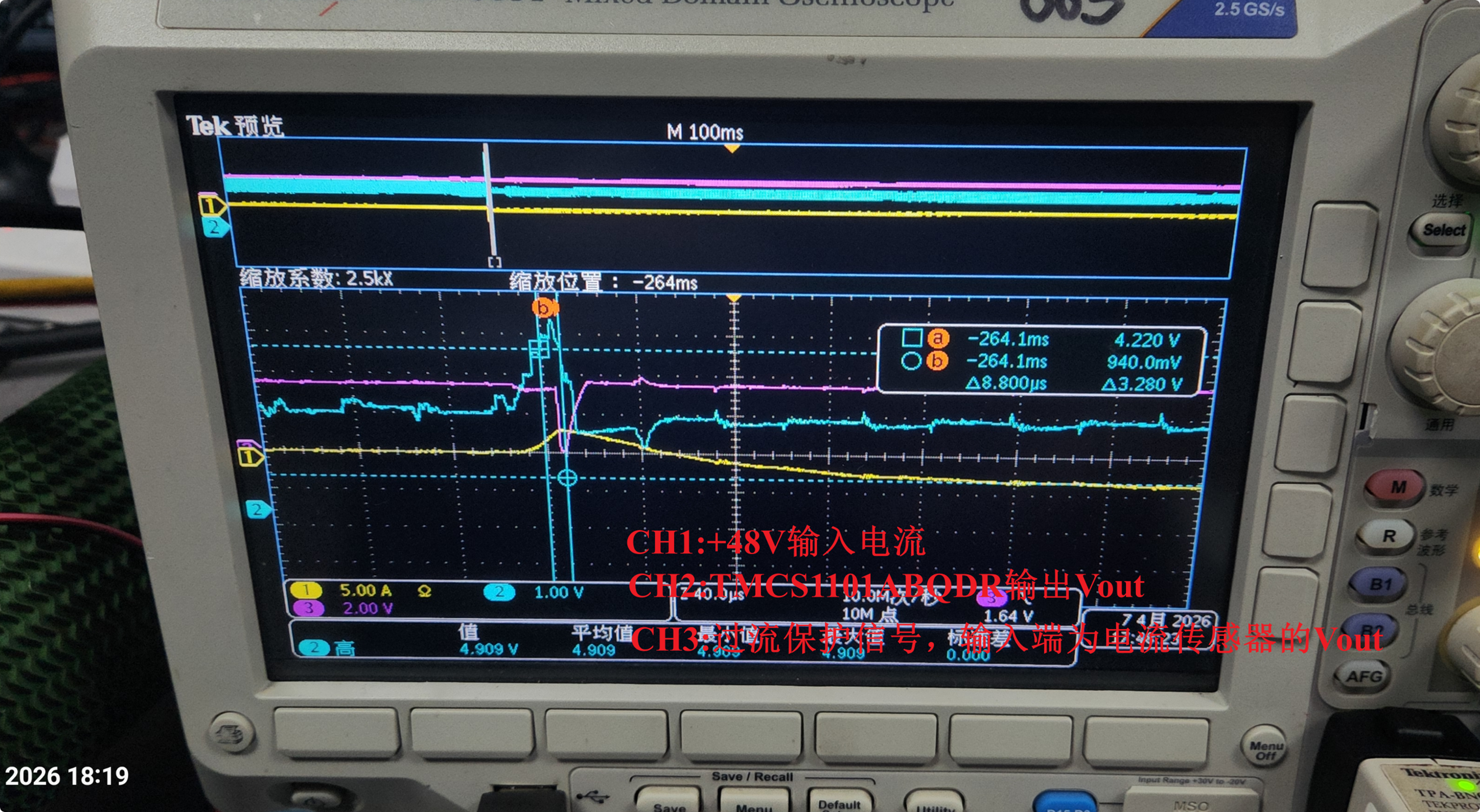
1. When the drive with motor operates under no-load conditions without additional loading, the Vout signal sent by TMCS1101A1BQDR is normal and will not falsely report a fault.
2. When our drive operates with a motor under rated load, at the moment of drive startup, the Vout signal emitted by TMCS1101A1BQDR may reach the comparator threshold, triggering overcurrent protection. This should be considered an abnormal phenomenon.

The overcurrent protection parameters are as follows:
1. The rated load of the driver is 5A;
2. The design point of the overcurrent protection threshold is 35A

The first two images below show a multi-axis low-voltage servo driver (+48V) DC+ high-side current sampling overcurrent protection circuit implemented using the TMCS1101A1BQDR current sensor chip. However, during actual testing, false fault reports occurred. Please help identify the cause of this issue and provide some solutions. Thanks!
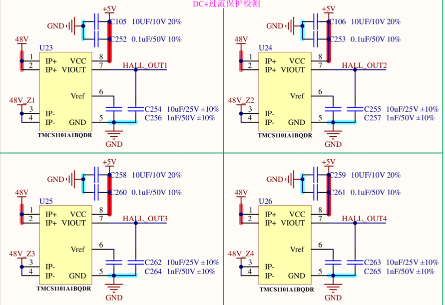
 

image.png

image.png

image.png

  • Reed, 

    My guess as to what is happening here is that upon loading the motor, current flow on the board is likely leading to additional external fields adding error. Our first generation of devices did not contain any form of ambient field rejection, so any large current flows on the board can lead to possible error in the device. This application report walks through these various challenges and shows how to mitigate them for these devices. Alternatively, our second generation of devices, such as the TMCS1123 have built in ambient field rejection that protect the output from these additional external field contributions. 

  • I want to know more about the underlying principles. For example,Why doesn’t this issue occur when used in in-line current sensing, even not occur in 380VAC servodrivers, but does occur when used in high-side DC-link current sensing in multi-axis low-voltage(+48V) servo drives?

  • Erica, 

    If my theory above is correct, it will not be in relation to the application itself, but rather the individual effects of the layout, current magnitudes and proximities to the sensor, and how well those items covered in the document are mitigated. Would it be possible to view the layout here?