TDC7200: Timing between Trigger and Start

Part Number: TDC7200

Hello TI Support Team!

I am working with the TDC7200 for a ToF Application.  I tried to use the Trigger to send an Impuls to a Cable an want to measure the time of the reflexion. 

The Datasheet states that the Time between Trigger to Start is about 5ns.  I can´t confirm this. I am searching now for a whole day, why my measurement isn´t starting. 

I tried to start and stop with a pin from my µC, it works, becaus the µC had a delay of 2µsec between Trigger and Start.  Next I add a RC Delay to the Trigger output ,(in the Delay Time from the µC) and the measurement was also starting. So I reduce the Delay step by step. So I found out that there must be a delay of approximately 300 ns between the trigger and the start. Otherwise the ClockTimer will not start the measurement. 

The tricky part is, that the 5ns at the start is enough, to put down the Trigger to low again.


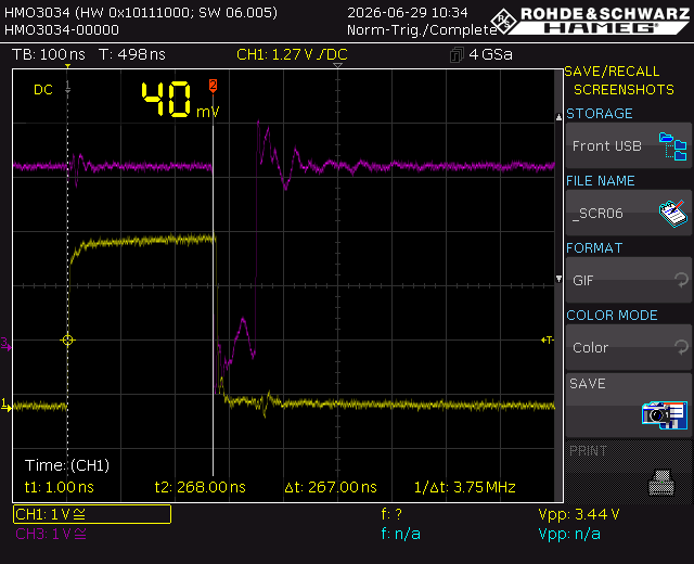
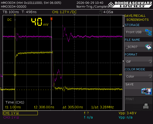
Yellow is the Trigger Output, purple is the Start and Stop Pin after a Comparator.  

In this case the measurement will not start
_SCR06.GIF   

In this case the measurement is starting.
_SCR07.GIF

  • Hi Martin,

    Thank you for posting to the Sensors forum!

    Looking at your Start/Stop signal, it doesn't look like the signal is as clean as it should be. I would expect it to have less noise. Is there a reason that the signal seems to have some small spikes?

    Best,

    ~Alicia

  • Hello Alicia!

    It´s ver 0.1 of my Application Protoboard and I had to make some modifications. Now I removed all unnecessary components. My setup now:

    I am going from the TDC7200 Trigger output into the trigger input of my "arbitrary function generator" (Tektronix) and send a 500ns sec Impuls with a Delay to the Start and Stop Pin. Start is at the riding edge, stop at the falling edge. Measure Mode is 2. The Signals are looking much better, but the result is the same. TDC Clock is 8MHz from an active Oscillator.  

    It works with a delay >300ns and never works with a Delay <250ns and in between it works sometimes.

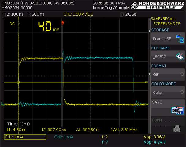
    Yellow = Trigger from TDC7200

    Cyan= Start/Stop from my AFG (at the TDC Input)

    Delay ca 250ns. Measurement is never working. No Interrupt of TDC. INT_Status Reg = 0x00

    Here is the Edge of the working Point: Interrupt of TDC is always Coming  INT_Status Reg = 0x19

    I also have valid values in the Clock and Time Register. 

    Do you have any Measurements wherethe TDC is working with a 5ns Delay as defined in Datasheet? 


  • Hi Martin,

    In addition to the register settings that you have mentioned, can you share your full register configuration?

    Best,

    ~Alicia

  • Hi Alicia! 

    Shure, I didn´t change anything yet, so the Register are all in the Reset State  

    Before the measurement after Initialisation.

    TDC7200_Complete:
    TDC7200 Config1: 0x00
    TDC7200 Config2: 0x40
    TDC7200 Int Status: 0x00
    TDC7200 Int Mask: 0x07
    TDC7200 Coarse Counter Overflow High: 0xFF
    TDC7200 Coarse Counter Overflow Low: 0xFF
    TDC7200  Clock Counter Overflow High: 0xFF
    TDC7200 Clock Counter Overflow Low: 0xFF
    TDC7200 CLOCK Counter STOP Mask High: 0x00
    TDC7200 CLOCK Counter STOP Mask Low: 0x00
    TDC7200 Time1: 0x000000
    TDC7200 Clock Count1: 0x000000
    TDC7200 Time2: 0x000000
    TDC7200 Clock Count2: 0x000000
    TDC7200 Time3: 0x000000
    TDC7200 Clock Count3: 0x000000
    TDC7200 Time4: 0x000000
    TDC7200 Clock Count4: 0x000000
    TDC7200 Time5: 0x000000
    TDC7200 Clock Count5: 0x000000
    TDC7200 Time5: 0x000000
    CALIB1: 0x000000
    CALIB2: 0x000000

    After a Trigger without a measurement there are the same values. 

    When the measurement is working the Register looks like this. 

    TDC7200_Complete:
    TDC7200 Config1: 0x12
    TDC7200 Config2: 0x40
    TDC7200 Int Status: 0x19
    TDC7200 Int Mask: 0x07
    TDC7200 Coarse Counter Overflow High: 0xFF
    TDC7200 Coarse Counter Overflow Low: 0xFF
    TDC7200  Clock Counter Overflow High: 0xFF
    TDC7200 Clock Counter Overflow Low: 0xFF
    TDC7200 CLOCK Counter STOP Mask High: 0x00
    TDC7200 CLOCK Counter STOP Mask Low: 0x00
    TDC7200 Time1: 0x0002B9
    TDC7200 Clock Count1: 0x000004
    TDC7200 Time2: 0x000286
    TDC7200 Clock Count2: 0x000000
    TDC7200 Time3: 0x000000
    TDC7200 Clock Count3: 0x000000
    TDC7200 Time4: 0x000000
    TDC7200 Clock Count4: 0x000000
    TDC7200 Time5: 0x000000
    TDC7200 Clock Count5: 0x000000
    TDC7200 Time5: 0x000000
    CALIB1: 0x00087B
    CALIB2: 0x0054BD

    I found something in the datasheet.

    8.4.1 Calibration 

    In order to compensate for these errors and to calculate the actual LSB value, calibration needs to be performed.
    The TDC7200 calibration consists of two measurement cycles of the external CLOCK.

    With my 8MHz Oscillator, this 2 Clock Cycle are 250ns. Is it possible that the start is ignored during this time?

    Best Regards. 

    MArtin


  • I just found Out that when the measurement is not starting the register doesn´t look like after the initialisation. 

    Config1 is different. so here is the full register set, when measuring is not Starting:

    TDC7200_Complete:
    TDC7200 Config1: 0x13
    TDC7200 Config2: 0x40
    TDC7200 Int Status: 0x00
    TDC7200 Int Mask: 0x07
    TDC7200 Coarse Counter Overflow High: 0xFF
    TDC7200 Coarse Counter Overflow Low: 0xFF
    TDC7200  Clock Counter Overflow High: 0xFF
    TDC7200 Clock Counter Overflow Low: 0xFF
    TDC7200 CLOCK Counter STOP Mask High: 0x00
    TDC7200 CLOCK Counter STOP Mask Low: 0x00
    TDC7200 Time1: 0x000000
    TDC7200 Clock Count1: 0x000000
    TDC7200 Time2: 0x000000
    TDC7200 Clock Count2: 0x000000
    TDC7200 Time3: 0x000000
    TDC7200 Clock Count3: 0x000000
    TDC7200 Time4: 0x000000
    TDC7200 Clock Count4: 0x000000
    TDC7200 Time5: 0x000000
    TDC7200 Clock Count5: 0x000000
    TDC7200 Time5: 0x000000
    CALIB1: 0x000000
    CALIB2: 0x000000

  • Hi Martin,

    Based on section 8.4.1, I do believe that the device is waiting for calibration to be completed before being able to accept the Start signal. Which makes sense given that you are only able to see measurements after a delay of 250ns between the trigger pulse and start pulse.

    Best,

    ~Alicia

  • OK, Thank you.

    You should correct that in the datasheet at the "Recommended Operating Conditions" section on page 6.   

    best wishes

    Martin