FDC1004EVM: FDC1004EVM: unnormal Sampling and Output Rate

Part Number: FDC1004EVM
Other Parts Discussed in Thread: FDC1004, MSP430F5529

Hello,

I am using FDC1004 EVM board with Sensing Solution GUI 1.10.0 and I have 2 problems. Actually, I have found similar problems asked in the forum 5 months ago, but the solution doesn't solve my problem. 

1) Data streaming does not work unless all 4 channels are enabled for reading. The settings are shown below, and data streaming has started, but no data has shown in the figure, and the corresponding CSV has no data.

 image.png

 image.png

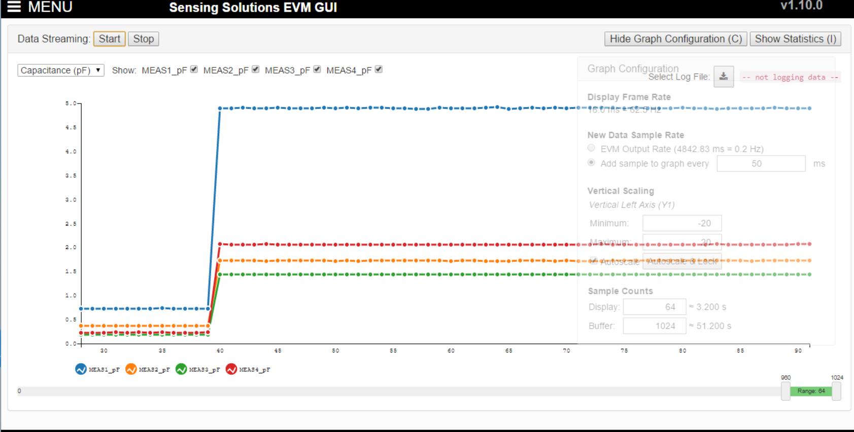
2) This is my main problem. The plotting speed is too slow, so as the rate in the CSV. It seems that the  rate shown in the figure and CSV is around 5Hz, and I have selected the 400Hz sampling rate. No matter how I change the setting, the final rate is similar. My final aim is to have the sampling rate at least 30Hz.  I also show the corresponding settings below, you can check. 
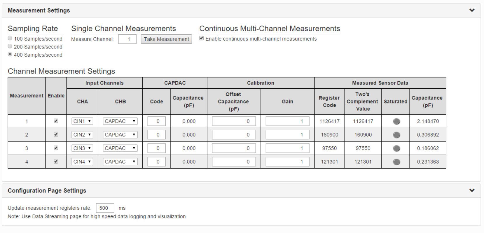
image.png

image.png

Thanks for your kind attention and I hope to have your answers.

  • Hi Heng,

    Thank you for posting to the senors forum! Do you have the latest version of the sensing solutions gui installed along with the most recent firmware update? 

    Best,

    Amanda 

  • Thanks for your kind reply. After updating the firmware, these two problems have been solved. 

    However, a new problem has occurred. The GUI reports an EVM output rate of approximately 100 Hz, and the CSV timestamps also indicate intervals about 10ms. However, when the recording duration is measured with an external stopwatch, a 10-second recording contains only about 500 rows of four channel data, corresponding to an actual sampling rate of approximately 50 Hz per channel. Therefore, the GUI-reported time appears to run about twice as fast as real time.

    I wonder how to solve this problem and I hope to have your new answers.

  • Hi Heng,

    I am glad that was able to resolve your first two problems. Can you please try configuring the device to sample only one channel at 100 Hz. If the sampling rate in the CSV matches the GUI report, the issue may be caused by the data throughput limit when multiple channels are active.

    Best,

    Amanda 

  • Hi Amanda,

    The result is the same. After configuring the device to sample only one channel at 100 Hz, the real sampling rate shown in the graph and the CSV is about 50 Hz. The settings are shown below, and as you can see in Figure 2, there are only around 500 counts in about 10 seconds.

  • Hi Heng,

    Thank you for trying this. Can you please change the update measurement registers rate from 500 ms to to 10ms.

    Best,

    Amanda

  • Hi Amanda,

    It seems that I can't change the update measurement registers rate to 10 ms, the minimum number is 100 ms. After changing to 100ms, the result is still the same.

    By the way, I am thinking whether the problem is the evaluation kit or the GUI. If the problem is GUI, maybe I can use another MCU board, for example Arduino, to control the evaluation board?

  • Hi Heng,

    I do agree that this is more than likely related to the GUI rather than the evaluation kit. You are welcome to try using another MCU but I would not be able to provide any software support. We do have reference code to use instead of the GUI for the FDC1004, would you be interested in using our code examples to control the evaluation board?

    Best,

    Amanda 

  • Hi Amanda,

    If the example code can control the four channels simultaneously with more than 30 Hz, and the clock is correct, I would love to use the example code directly.

  • Hi Heng,

    Sorry for the late reply. Please allow me some time to put together some coding resources to assist you. I will respond by end of day today.

    Thank you for your patience,

    Amanda 

  • Hi Heng,

    I am unable to find an example of this specific functionality; however, I was able to find code examples for reading the data via i2c for the FDC1004 as well as learning resources for clock programming and i2c control for the microcontroller used in this evaluation kit. The FDC1004 code example I am referring to is available for download on our website: FDC1004QEVM Evaluation board | TI.com. It is called "Capacitive Sensing Sample Code", you should be able to open the ino file in our CCS application to view the code. For additional resources on how to control the MSP430F5529 microcontroller please reference the resource explorer section of our TI developer zone: Resource Explorer. The resource explorer provides training on using the MSP microcontroller in the MSP430 Academy and code examples in the embedded software section. Please let me know if you need help navigating the included resources. 

    Best,

    Amanda