This thread has been locked.

If you have a related question, please click the "Ask a related question" button in the top right corner. The newly created question will be automatically linked to this question.

TMP512 - Trouble Getting Reading from Remote Sensors

Other Parts Discussed in Thread: TMP512, DXP

I've got a small board with 2 TMP512's that I'm trying to use for remote temperature sensing using discrete transistors.  I am not using the power supply monitor functionality of the TMP512 at all.  In my design both Vin+ and Vin- are tied to ground and I've disabled the shunt measurement ADC in the Shunt Measurement Configuration Register (0x00).  I can read the local temperature result register and it seems to be working great, however when I attempt to read the remote result 1 or 2 registers, bit 0 indicating the Diode Open Flag is always set (I have the remote channels configured for continuous conversion).  I'm not sure what I'm doing wrong.

Here are some more details about my design:

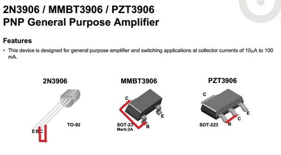
  • My remote sensing transistors are standard 2N3906 BJT's that are diode connected as shown in figure 21 b of the datasheet.  
  • I'm using 560pF filter capacitors for both remote channels, although the sensors are not being placed near any other electrical devices so noise should not be an issue. 
  • I'm using subregulator "Configuration 3" as shown in figure 22 of the datasheet, my V+ is 5V.
  • After reading the Sensor Fault section of the datasheet I checked the voltage at DXP1 and DXP2 and both fluctuate between 1.23V and 1.29V.  This is clearly less than (V+) - 0.6V = 5V - 0.6V = 4.4V in my case.
  • All of my 2N3906's are brand new, but I've tried 6 of them just to be sure.
  • I've tried reseting and then reconfiguring the TMP512 multiple times. 
I'm really scratching my head on this one, does anyone have any suggestions?
  • Hi david,

    Thanks for your interest in the TMP512...I am having my team take a look at your request and we will repoly to you as soon as we have a few ideas for you to try.

    Best regards,

    Ed Mullins

    Applications Manager - AIP Sensinig Products

  • Hello David,

    Thank you for the detailed explanation of your settings and configurations. I did go ahead and replicate your settings on my TMP512 EVM boad and your settings with respect to disabling shunt measurement ADC, continuous conversion, etc seem to be correct.  They seem to work fine on my EVM setup. For us to be able to solve this issue I would like you to check on a few things here:

    1. Since you are using the  2N3906 BJT's. Can you please double check and make sure that Base and Collector are connected together. (As shown in the attached picture)  

    2. Please also make sure that the 2N3906 BJT's Emitter is connected to DXP while Collector-Base are connected to DXN (When I revere the connections I do get the Diode open flag - SET and the Average voltage is between DXP and DXN close to 1.2V - just like you mentioned)

    3. Can you provide me more information on how you are measuring the voltage between DXP and DXN (oscilloscope, multimeter)?

    4. If step 1,2 dont solve your issue it would be of help if you could provide me the Series resistance (Rs) of DXP to Emitter and DXN to Collector-Base

    Hope this helps to solve your issue! 

    -Abhi


  • As I mentioned before I have 2 TMP512's on my board and I only had transistors connected to one of them. It turns out that I've been talking to the wrong TMP512 the whole time.  Once I started using the right I2C address I started getting correct remote temperature readings.

    I feel really stupid right now... Anyway I knew it had to be something simple, thanks Edward and Abhi.

  • It's very normal to miss a few details here and there. Glad we could get your issue resolved. 

    Regards,

    Abhi