This thread has been locked.

If you have a related question, please click the "Ask a related question" button in the top right corner. The newly created question will be automatically linked to this question.

TMP006 register 01h problem

Other Parts Discussed in Thread: TMP006

Hi,

I have used hot gun to mount 6 TMP006 chips on my new boards. The hot gun is Steinel 3483. It was set to 310 degree. Solder flux was applied before soldering. The flux type is Alpha NR-205. The flux was cleaned by ultrasonic cleaner later.

Afterwards, I tested TMP006 in the lab. I confirmed serial bus firstly. The device ID (register FFh) always returned 0x0067, which was right. One of 6 TMP006 chips returned 0x6D94 (register 01h). The value meant 219.16 degree of ambient physical temperature. It seemed extremely high. It was impossible in the lab. What was problem?

BRs,

Luo

  • Hello Luo,

    Thanks for posting your issue on reading high values on temperature register. I will discuss this issue with our temp sensors team and get back to you soon.

    Regards,

    Abhi

  • Hi Luo,

    We would like you to try a few things to further troubleshoot this issue:

    Can you please confirm for the device in question:

    • Where is ADR0 connected?
    • Where is ADR1 connected?
    • What voltage is applied to V+ pin?
    • What power supply bypass capacitance is used? (there should be a bypass capacitor at each of the TMP006's)
    • What is the temperature of the ambient environment, i.e. PCB? (The local temperature sensor should be at the same temperature as the PCB)
    • What values of pull-up to V+ resistor is used for:
    •      DRDY
    •      AO
    •      A1

    I'd like you to re-solder the TMP006 in question...Please add some flux and reflow the part...it might be that somehow there is a high impedance connection after the first attempt at solderingthe device to the PCB. I have attached document "TMP006 Layout and Assembly Guidelines sbou108.pdf" for the recommended flux, reflow profile and cleaning recommendations.

    After reflowing the device please go ahead and please read all 5 registers and send us the results.

    Should the local temperature still read well above what you would expect, please repeat the read on the Tambient register and send us an oscilloscope photo of the SDA, SCL and DRDY and V+ pins.

    Best regards,

    Ed Mullins

    Applications Manager

    AIP - Sensing Products

    6175.TMP006 Layout and Assembly Guidelines sbou108.pdf


  • Hello  Luo,

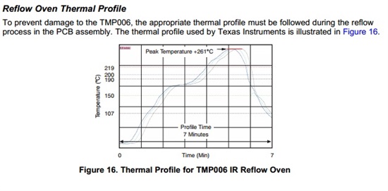
    Also, adding on to what Ed has just explained, if you refer to the following pic from the document that he pointed out:

    As see in the above graph the temperature during the re-flow process is not to exceed 261 degC. Since you mentioned that hot rot temperature was set to 310 deg C, this most likely damaged your part.

    Regards,

    Abhi

    Applications Engineer

    Temperature Sensors

  • Hi,

    The device connection is listed below.
      1)ADR0 and ADR1 are connected to ground.
      2)DRY is open.
      3)V+ is 3.86V
      4)Pull-up resistors are 10K
      5)0.1uF bypass capacitor is used.
    I can confirm PCB temperature is less than 25 degree. Regarding waveform, I am sorry that it is not available so far.

    I think serial bus has no problem because chip ID was always right even under stress test. Furthermore, register 00h could follow object temperature.
    Register 01h could also change a bit more except extreme huge value. I suspect that pin A2 (AGND) is floating because of solder issue. Does it result in extreme high local temperature? Could you please do such test to see what will happen? Thanks.

    BRs,

    Luo

  • Hi Luo,

    Thank you for the information...everything so far with your setup seems correct.  Keep in mind with the DRDY pin floating the DRDY function will not work properly, but if you are not using that function this will be OK.  We are setting up for the floating AGND test and as soon as I have results I will send them.

    Best regards,

    Ed Mullins

    Applications Manager

    AIP - Sensing Products

  • Hi Luo,

    I had my team make the following tests per your request:

    • Float both AGND and DGND - result = no communication or proper functionality - this is expected
    • Float AGND with DGND tied to ground - result = communication is normal, local temp sensor result is normal, increased error of object temp - this is expected
    • Float DGND with AGND tied to ground - result = no communication or proper functionality - this is expected

    To summarize we were not able to reproduce the issue you see on your board.  Given your situation I have the following recomendation...because the original solder profile used to attach the devices to the PCB is likely to have exceeded TI's recommended solder reflow profile the part may have been damaged.  Please replace the one sensor that is failing, ensuring that the recomended reflow profile and cleaning process is within the recommended guidlines.  You are welcome to return the failing product to TI for a failure analysis if you feel this information will be helpful in your evaluation.  If you do decide to return the device you can contact either your local TI sales person, distributor or send me an email and I can provide to you the instructions for returning a product for analysis.  My email address is mullins_ed@ti.com

    Best regards,

    Ed Mullins

    Applications Manager

    AIP - Sensing Products


  • Hi Mullins,

    Thanks for your fast test. I hope the issue is a single issue. Your recommendation is good to me. But I have other higher priority works. I will contact TI after I make the board volume production. Thanks.

    BRs,

    Luo