This thread has been locked.

If you have a related question, please click the "Ask a related question" button in the top right corner. The newly created question will be automatically linked to this question.

TMP006EMV project

Other Parts Discussed in Thread: TMP006

Hi,

I'm working on a project , and we are trying to measure (to scan ) a PCB temperature . Eg. we have 10x10 mm board and a like to have 100 point's of temp. measure(1x1 mm).

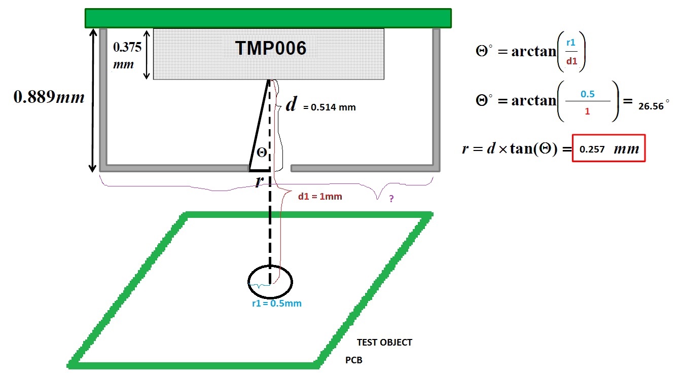
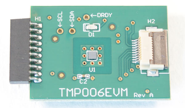
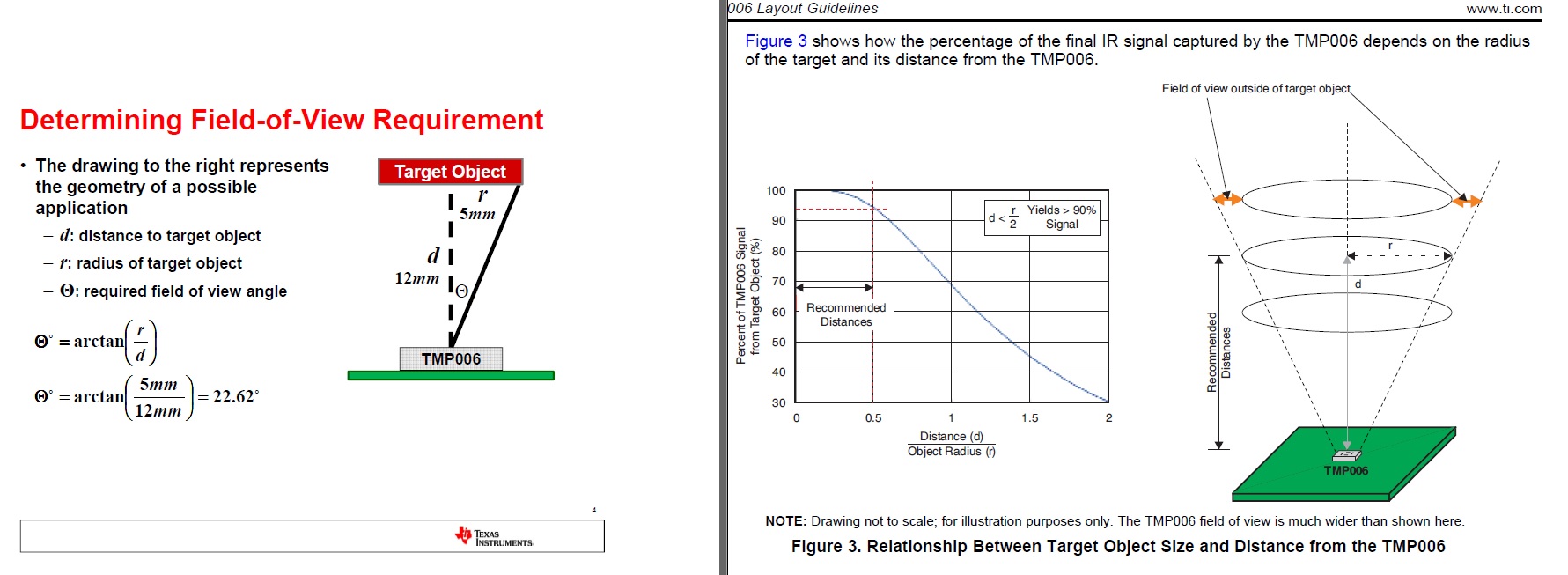
The TMP006EMV should be 1 to 5 mm away from the target object. I calculated the cover size and attached my calculation for 1mm distance.

1) Can you pleas check the calculation if it's correct?

2) What is the size of cover marked with "?" on the picture?

3) Currently we are using TMP006EMV but in the future we are going to try connect the module on our board without the USB-DIG and I would to know what is the output data of TMP006 on the I2C, It's the object temperature or voltage and what code do I need to use to convert the voltage from I2C to object temperature , do I need to use the TRANSIENT CORRECTION and how?

Regards,

David.

  • Hello David,

    Thank you for posting your TMO006 questions. I will get back to you with answers soon..

    Best Regards, 

    Abhi Muppiri

    Applications Engineer

    AIP- Sensing Products

  • Hi Abhi,

    Did you found an answer to my questions?

    Regards,

    David.

  • Hello David,

    1. The calculation is correct. But I'm just wondering from where you got the 0.375mm as the height of the TMP006. The actual sensor lies at the bottom of the chip and due to the way this part is being soldered on to the board you can expect the sensor to be at around 0.25mm (0.15-0.35) height from the board (For more info on this please refer to the Machanical Data section of the data sheet).

    So if you consider this to be around 0.25mm your get r ~0.32mm. For better accuracy please make sure your inner surface of the cap is not metallic or shiny.

    2. The size of the cover should NOT matter.

    3. If you refer to the TMP006 data sheet you will find that you get Vobject and Tambient by reading the registers 0x00 and 0x01 hex respectively. So the host device can access this information from the part through the I2C SCL, SDA lines. From this information can calculate the Tobject temperature by using the attached C code. This also takes care of transient correction when you include this in the host processor.

    Can you provide more details of your project? This will help me better understand your requirements. Does this go into some sort of end user application or is it like a research/university  project?

    Best Regards,

    Abhi Muppiri

    Applications Engineer

    AIP- Sensing Products

    Texas Instruments

  • Hello Abhishek,

    Thanks for your help.

    ->But I'm just wondering from where you got the 0.375mm as the height of the TMP006.

    I got it form the document attached to the post.

    6076.Video_TMP006 field of view.pdf

    ->Can you provide more details of your project? This will help me better understand your requirements. Does this go into some sort of end user application or is it like a research/university  project?

    It is currently a research/university project , and I'm trying to connect the module on the picture to a ti c2000 launchpad.

    Later we are going to build or own main board with TMS320F28035 and at end should be and working product with own GUI.

    Regards,

    David.

  • Hello David,

    Glad I could help you out on this and Thanks for the Information!

    Best Regards,

    Abhi Muppiri

    Applications Engineer

    AIP- Sensing Products

  • HI,

    Quick question.

    If I use d=12mm and r=5mm like in the picture

    that means d/r=12/5=2.4 => Signal from target object < 30 %.

    Is that true and if yes, is this a big problem?

    Regards,

    David.

  • Hello David,

    That is correct. In the given example you will be loosing about 70% of the signal. If your application supports, its good to try and make sure that your distance(d) is < r/2 there by making sure that TMP006 gets the maximum voltage change for change in the objects temperature.

    Best Regards, 

    Abhi Muppiri

    Applications Engineer

    AIP- Sensing Products

    Texas Instruments 

  • Hello Daivis,

    I have a suggestion for you...

    Along with choosing the right FOV you can also increase the TMP006 signal response by increasing the PCB's/Test objects emissivity. It will be better if you choose a PCB whose emissivity is high around 0.91 (Typically it ranges between 0.8-0.92). Another better alternative is to coat the surface of the test board with black color coating. This should improve the signal response considerably.

    Regards,

    Abhi