Please let me know three below about the directions for TMP006.
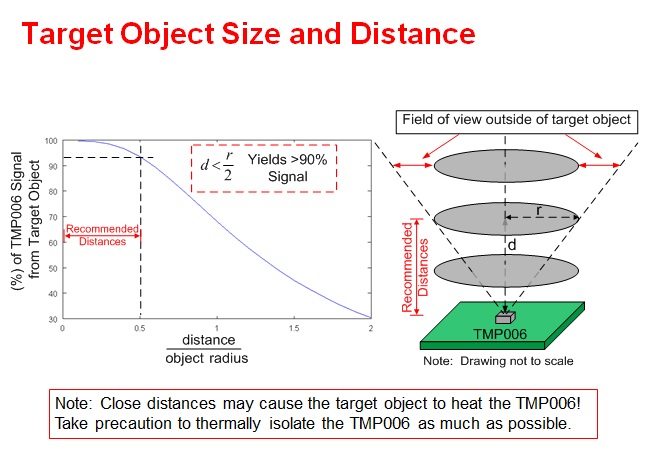
- Does measurement accuracy get worse in distance?
Are there related data and distance permitted then?
- How long [ maximum ] is the measurement temperature range of IR?
(It was writing to the register setup of a data sheet to 150 ℃)
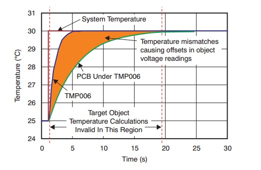
- Although cared about the measurement accuracy of IR sensor worsening by the rise of ambient air temperature (Local),
Does Fig. 3 of URL show the graph after the calibration was carried out below?
And if there is the method of maintaining the measurement accuracy of IR sensor, please let me know.
http://www.tij.co.jp/jp/lit/ug/sbou108/sbou108.pdf
Thank you for your consideration.