Hello
I am attempting to read/write to a TMP275 using an MSP430G2553 (Launch Pad), using the IAR compiler.
The TMP275 has 8K pullups to Vcc on SDA and CLK, stealing power from the Launch Pad.
The TMP275 address pins are tied to Vcc.
I can write and read the control register just fine...
When writing, then reading either TLow or THigh, the 1st byte works as expected, but the second byte always returns 0xFF.
I am aware the G2553 has IC2 capabilities, but I want to use/save the uart for a comm link so I am bit banging the IC2 to run the TMP275
IAR Code:
WriteTMP275IntToPointer( TMP275_7, TLOW_REG, 0x1230 );
Temp2 = ReadTMP275IntAtPointer(TMP275_7);
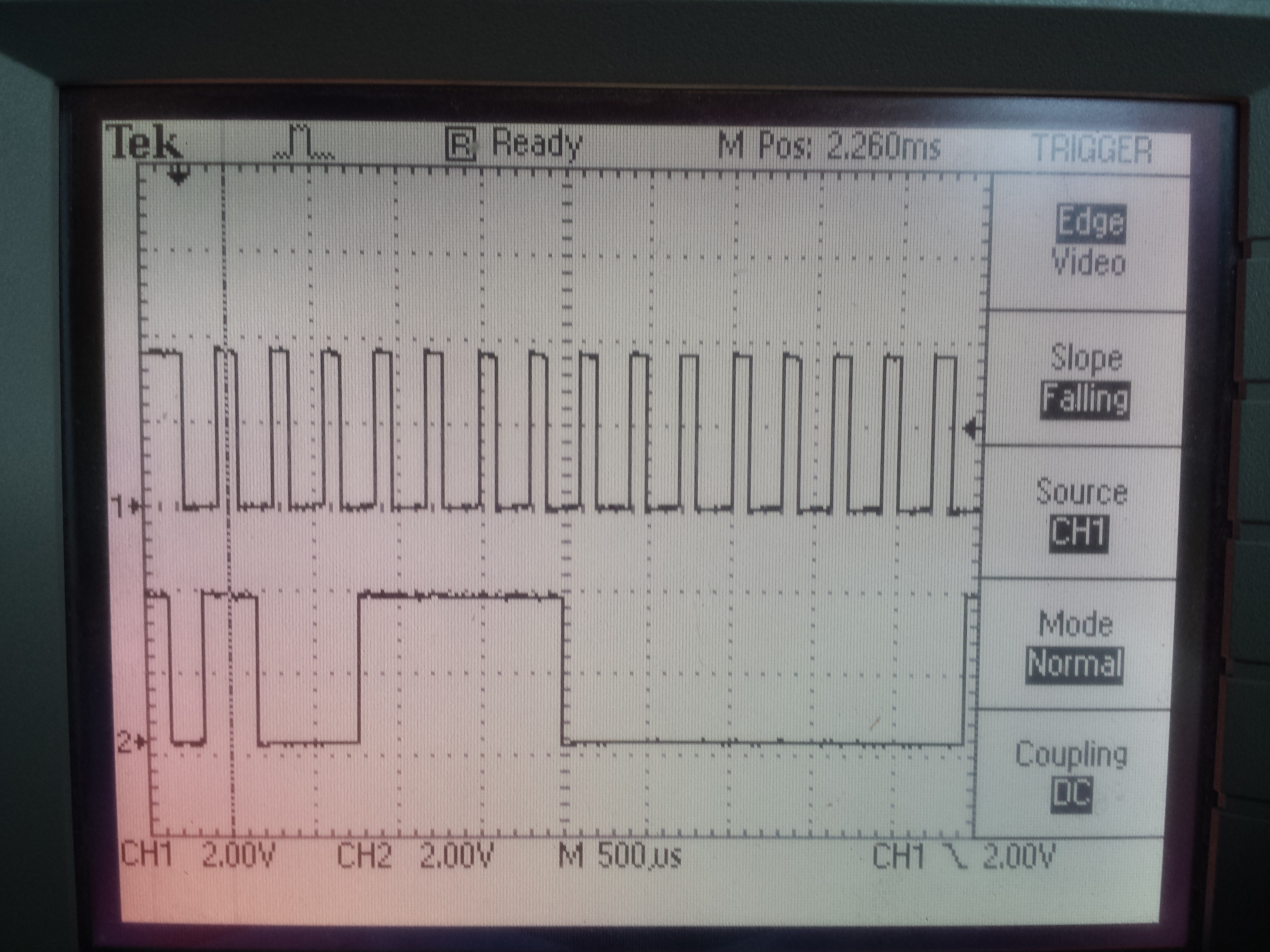
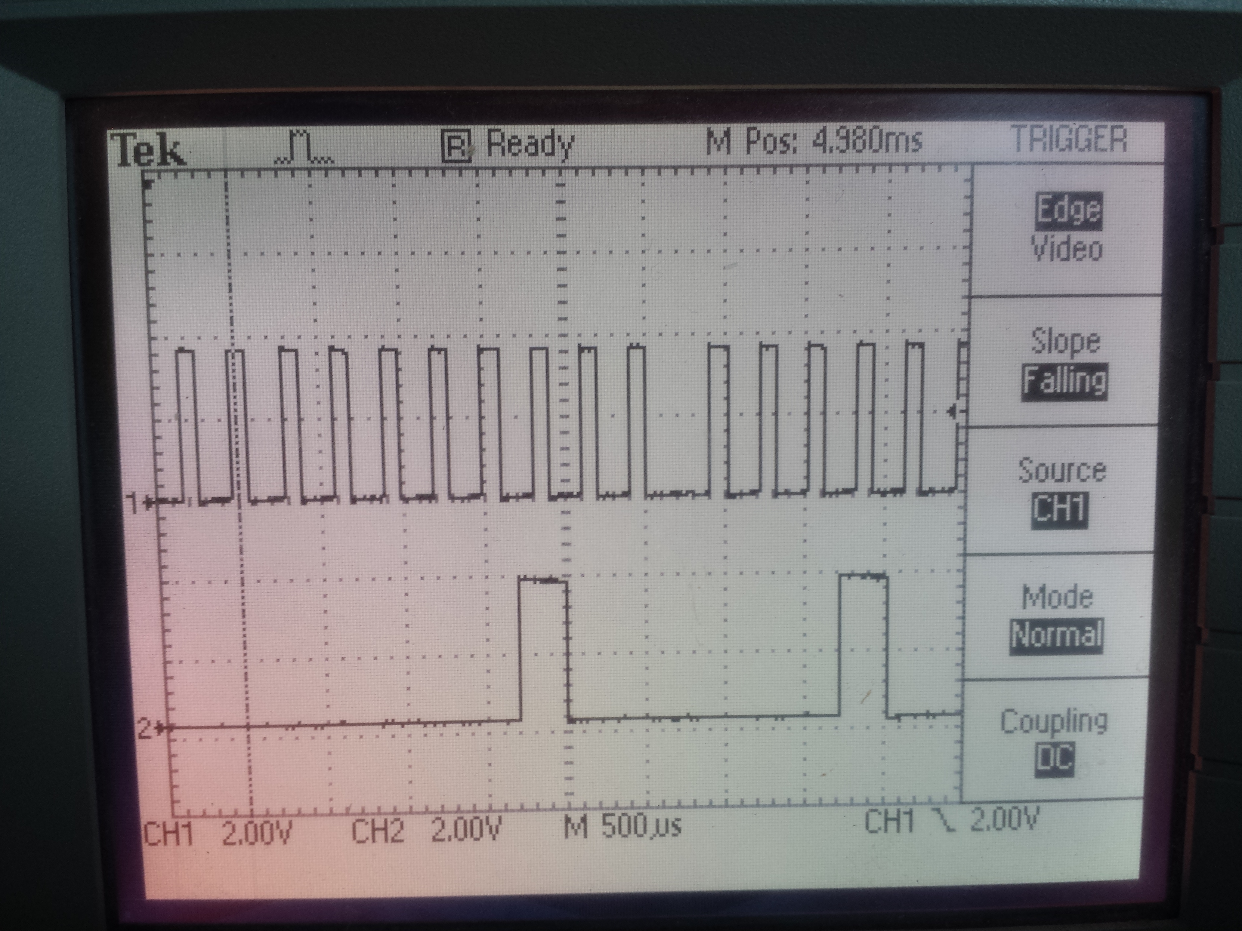
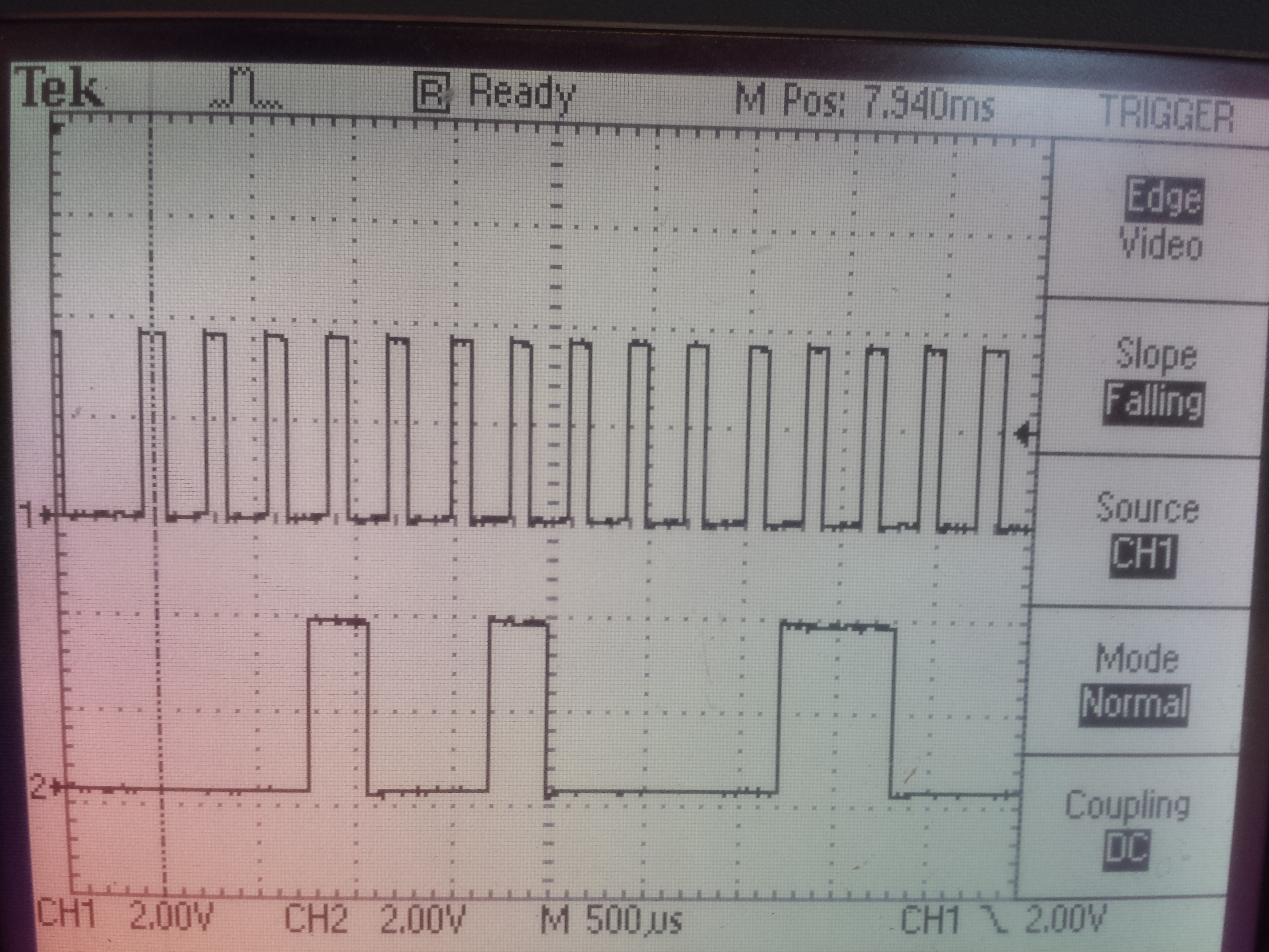
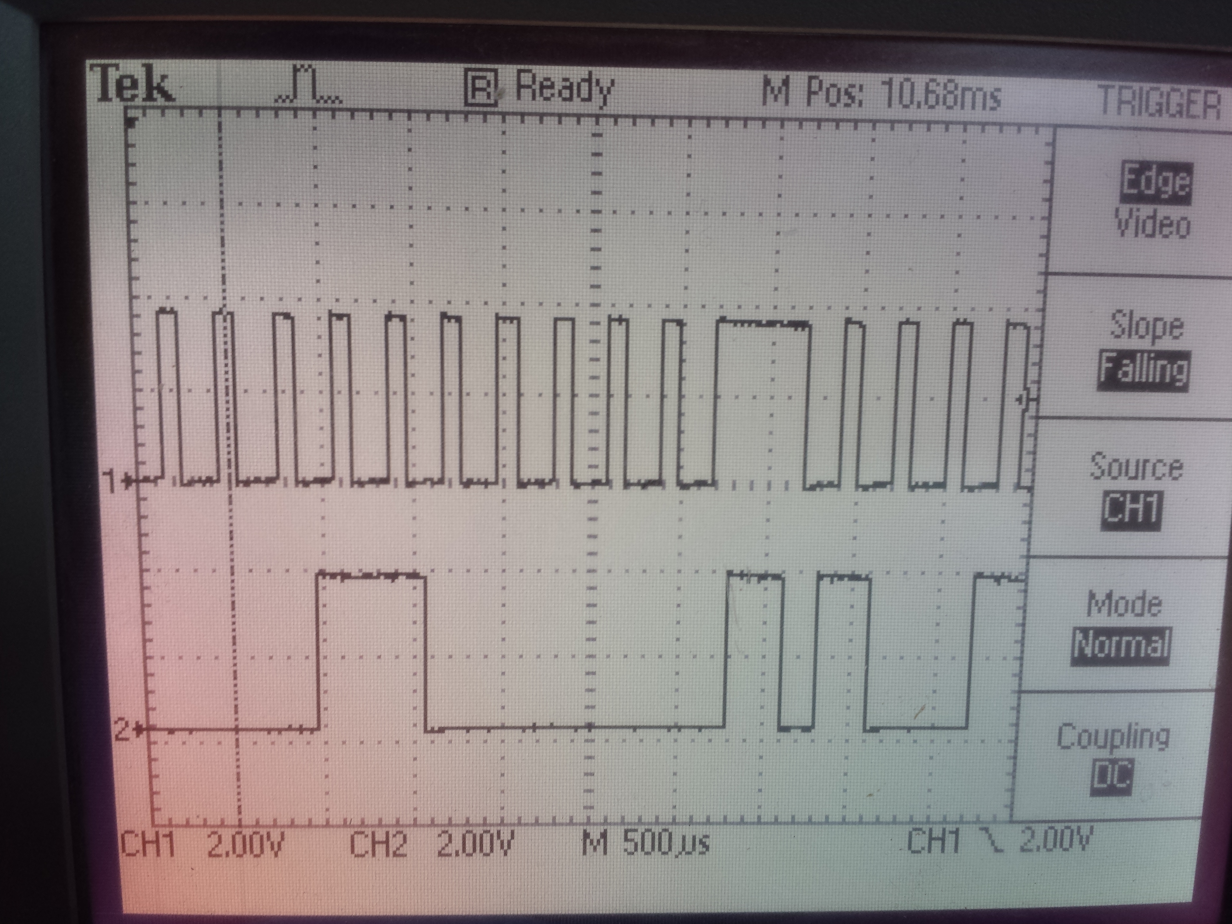
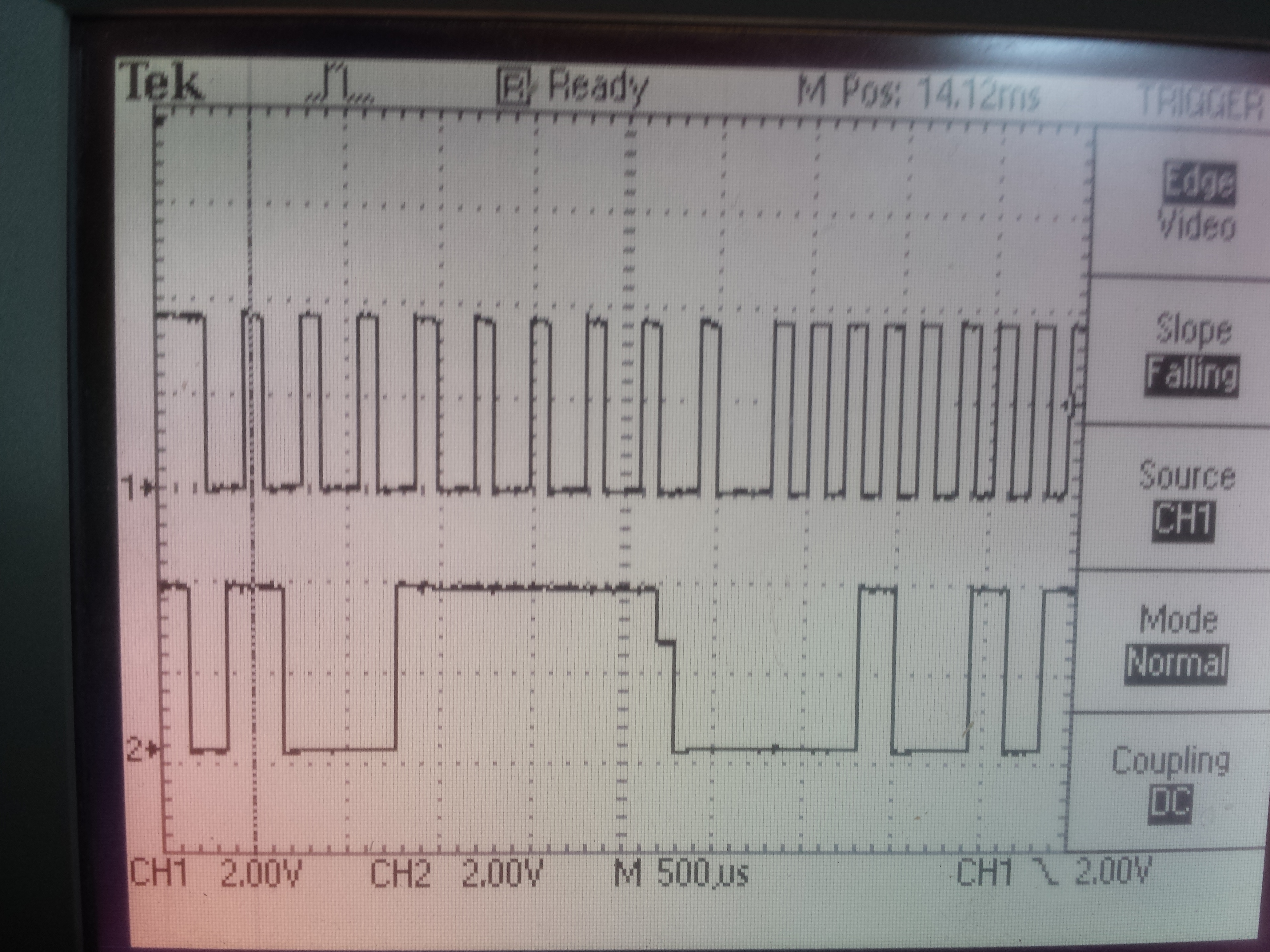
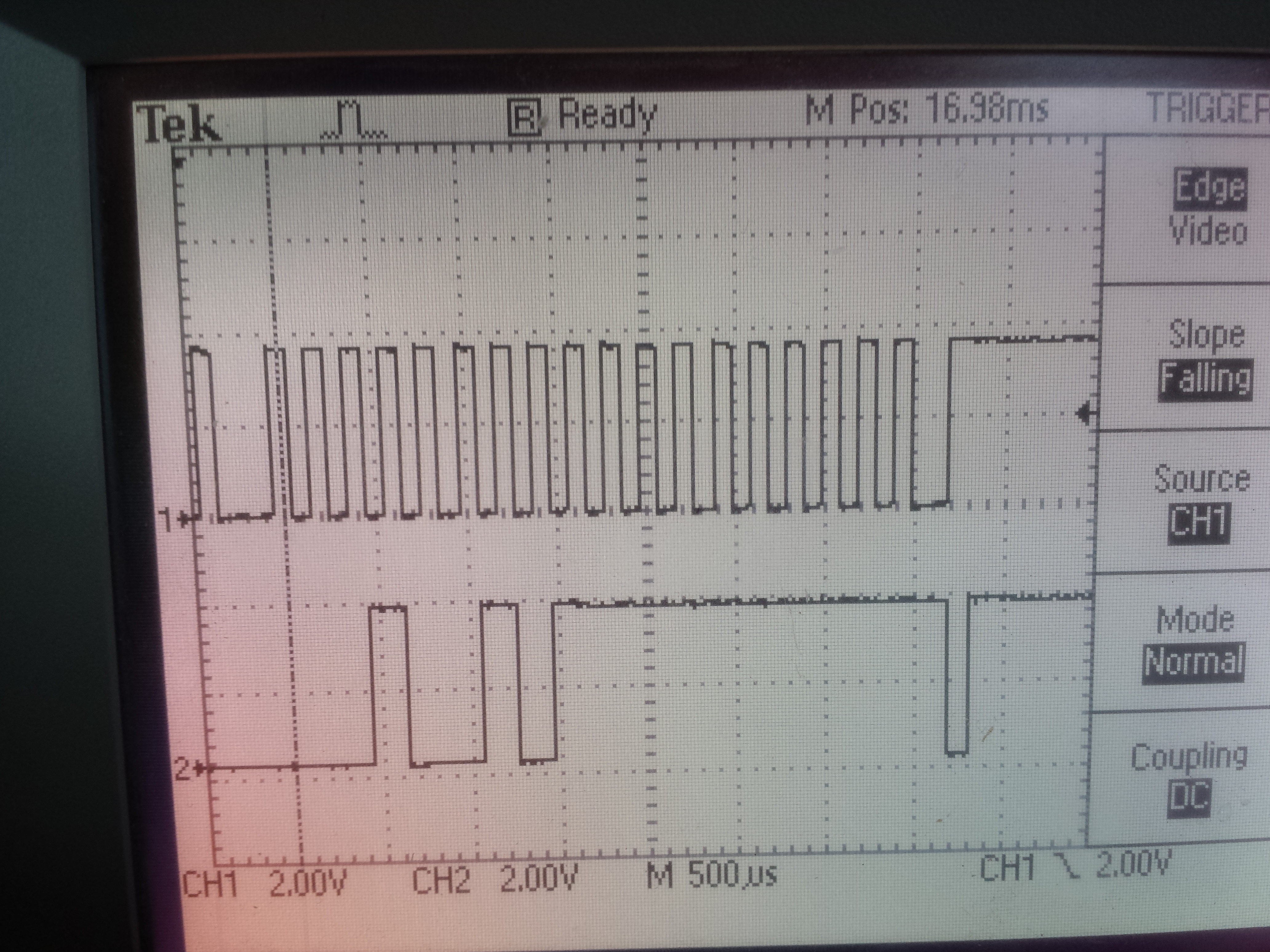
I have photos of my Oscope writting/reading the data, but at 25MB, zipped, it was to large to include here.
(I can email them individually to you, if you wish)
See the bottom of this file for the definitions of constants.
Thank you.
Where:
void WriteTMP275IntToPointer( unsigned char who, unsigned char DaPointer, unsigned int the_int )
{
long longint = (((the_int & 0xFF00) << 2 ) | ((the_int & 0x00F0) << 1));
MasterStart();
// write address, writing to pointer
for(unsigned char position = 0x80; position != 0; position = position >> 1 ) //A
{
if( 0 == ((who + WRITE) & position) )
{
SetSDALow
}
else
{
SetSDAHigh
}
Wait100US();
SetSCLHigh
Wait100US();
SetSCLLow
Wait100US();
}
SetSDALow
Wait100US();
SetSCLHigh
Wait100US();
SetSCLLow
Wait100US();
// Ack from TMP275 should show up here...
// set the pointer to config
for(unsigned char position = 0x80; position != 0; position = position >> 1 ) //B
{
if((DaPointer & position) == 0)
{
SetSDALow
}
else
{
SetSDAHigh
}
Wait100US();
SetSCLHigh
Wait100US();
SetSCLLow
Wait100US();
}
SetSDALow
Wait100US();
SetSCLHigh
Wait100US();
SetSCLLow
Wait100US();
Wait100US();
Wait100US();
// Ack from TMP275 should show up here...
// send the std config data via pointer
for(long position = 0x20000; position != 0x0000; position = position >> 1 ) //C
{
if(longint & position)
{
SetSDAHigh
}
else
{
SetSDALow
}
Wait100US();
SetSCLHigh
Wait100US();
SetSCLLow
Wait100US();
}
SetSDALow
Wait100US();
MasterStop();
Wait100US();
}
unsigned int ReadTMP275IntAtPointer(unsigned char who )
{
MasterStart();
for(unsigned char position = 0x80; position != 0; position = position >> 1 ) //F
{
if( 0 == ((who + READ) & position) )
{
SetSDALow
}
else
{
SetSDAHigh
}
Wait100US();
SetSCLHigh
Wait100US();
SetSCLLow
Wait100US();
}
SetSDALow
Wait100US();
SetSCLHigh
Wait100US();
SetSCLLow
Wait100US();
Wait100US();
Wait100US();
// Ack from TMP275 should show up here...
unsigned int ReturnValue = 0;
SetSDADirectionInput
for(unsigned char Counter = 0x80; Counter != 0; Counter = Counter >> 1) //G
{
SetSCLHigh
Wait100US();
if(ReadSDA != 0)
{
ReturnValue |= (Counter << 8);
}
SetSCLLow;
Wait100US();
}
SetSCLHigh
Wait100US();
SetSCLLow
Wait100US();
for(unsigned char Counter = 0x80; Counter != 0; Counter = Counter >> 1) //G
{
SetSCLHigh
Wait100US();
if(ReadSDA != 0)
{
ReturnValue |= Counter;
}
SetSCLLow;
Wait100US();
}
SetSCLHigh
Wait100US();
SetSCLLow
Wait100US();
SetSDALow
Wait100US();
SetSDADirectionOutput
MasterStop();
return ReturnValue;
}
void MasterStart( void )
{
SetSCLHigh
SetSDAHigh
Wait100US();
SetSDALow
Wait100US();
SetSCLLow
Wait100US();
}
void MasterStop (void )
{
SetSCLHigh
Wait100US();
SetSDAHigh
Wait100US();
}
// WHO
#define TMP275_0 0x90
#define TMP275_1 0x92
#define TMP275_2 0x94
#define TMP275_3 0x96
#define TMP275_4 0x98
#define TMP275_5 0x9A
#define TMP275_6 0x9C
#define TMP275_7 0x9E
#define READ 1
#define WRITE 0
// Registers
#define TEMP_REG 0
#define CONFIG_REG 1
#define TLOW_REG 2
#define THIGH_REG 3
// Configuration
#define SHUTDOWN_OFF 0x00 // Enables TMP275
#define SHUTDOWN_ON 0x01 // Shuts down TMP275
#define COMPARE_MODE_0 0x00 // changes state on every excursion
#define COMPARE_MODE_1 0x02 // generates a new interrupt on each excursion
#define POLARITY_ACTIVE_LOW 0x00 // alert is active low
#define POLARITY_ACTIVE_HIGH 0x04 // alert is active high
#define FAULT_QUEUE_1 0x00 // number of excursions before tripping alert = 1
#define FAULT_QUEUE_2 0x08 // number of excursions before tripping alert = 2
#define FAULT_QUEUE_4 0x10 // number of excursions before tripping alert = 4
#define FAULT_QUEUE_6 0x18 // number of excursions before tripping alert = 6
#define RESOLUTION_DOT5C 0x00 // Resolution = 0.5 degrees C or 9 bits
#define RESOLUTION_DOT25C 0x20 // Resolution = 0.25 degrees C or 10 bits
#define RESOLUTION_DOT125C 0x40 // Resolution = 0.125 degrees C or 11 bits
#define RESOLUTION_DOT0625C 0x60 // Resolution = 0.0625 degrees C or 12 bits
#define STD_CONFIG RESOLUTION_DOT0625C + FAULT_QUEUE_1 + POLARITY_ACTIVE_HIGH + COMPARE_MODE_0 + SHUTDOWN_OFF
#define SCL BIT3
#define SDA BIT4
#define Temp 0
#define Config 1
#define TLow 2
#define THigh 3
#define ReadSDA (P2IN & SDA)
#define SetSDAHigh (P2OUT |= SDA);
#define SetSDALow (P2OUT &= ~SDA);
#define SetSCLHigh (P2OUT |= SCL);
#define SetSCLLow (P2OUT &= ~SCL);
#define SetSDADirectionOutput (P2DIR |= SDA);
#define SetSDADirectionInput (P2DIR &= ~SDA);
#define SetSDAPullUp (P2REN |= SDA);
#define ResetSDAPullUp (P2REN &= ~SDA);