This thread has been locked.

If you have a related question, please click the "Ask a related question" button in the top right corner. The newly created question will be automatically linked to this question.

TMP112 I2C communication

Other Parts Discussed in Thread: MSP430G2553, TMP112

Hello,

I am using the TMP112 sensor in combination with the MSP430G2553 and have troubles getting the right temperature data. 

I am using the MSP DCO operating at 8 MHz which is also the SMCLK frequency. With a divider of 80, I get the I2C frequency of 100 kHz. The A0 Pin of the TMP112 is connected to ground, so that I have to address 1001000 = 0x48. I put those into the initI2C() function. My C-code looks as follows:

void initI2C()
{
    P1SEL |= BIT6 + BIT7;                                                                       // Assign I2C pins to USCI_B0
    P1SEL2 |= BIT6 + BIT7;                                                                    // Assign I2C pins to USCI_B0

    UCB0CTL1 |= UCSWRST;                                                              // Enable SW reset
    UCB0CTL0 = UCMST + UCMODE_3 + UCSYNC;                      // I2C Master, I2C Mode, synchronous mode
    UCB0CTL1 = UCSSEL_2 + UCSWRST;                                      // Use SMCLK, keep SW reset
    UCB0BR0 = 80;                                                                                 // fSCL = SMCLK/80 = ~100kHz
    UCB0BR1 = 0;
    UCB0I2CSA = 0x48;                                                                         // Set slave address
    UCB0CTL1 &= ~UCSWRST;                                                          // Clear SW reset, resume operation
}

As the initial address pointer value is 00 and pointing to the temperature register, I'm guessing it should be sufficient to enter the receive mode and collect high- and lowbyte from the RXBUFFER. For debugging, I am using a UART communication with the terminal program HTerm to verify my results. This is done by using the function sendByte and should work properly, as it was tested with reference values.

void I2C_TMP112_read()
{
    unsigned char temp;
    UCB0CTL1 &= ~UCTR;                         // Master Receive Mode
    UCB0CTL1 |= UCTXSTT;                      // send Start Condition
    while (!(IFG2 & UCB0RXIFG));             // Loop until I2C STT is cleared, slave acknowledge was received and RXBUFFER is ready
    temp = UCB0RXBUF;
    sendByte(temp);
    while (!(IFG2 & UCB0RXIFG));             // Loop until RXBUFFER ready
    temp = UCB0RXBUF;
    sendByte(temp);
    sendByte('\n');
    UCB0CTL1 |= UCTXSTP;
}

Now these are the results that I can see in HTerm:

11111111 01100000 00001010

Here, the last Byte 0x0A is correctly transmitted as the Linefeed byte '\n'. The problem is with the temperature data. Those values don't represent room temperature and I got the feeling that I was accessing the configuration register, although the values do not fit those of the initial configuration register after power up.

So I tried to set the address pointer manually to 00 with a second initialization function, so that the temperature register would be default for all readouts.

void I2C_TMP112_init()
{
    UCB0CTL1 |= UCTR + UCTXSTT; // Master Transmit Mode
    while (!(IFG2 & UCB0TXIFG));
    UCB0TXBUF = 0x00;
    UCB0CTL1 |= UCTXSTP;
}

But that didn't do the trick either. The following main function was used to get the results:

int main(void) {

    WDTCTL = WDTPW | WDTHOLD; // Stop watchdog timer

    initClock();
    initUART();
    initI2C();
    //I2C_TMP112_init();

    __bis_SR_register(GIE);

    while(1)
    {
        I2C_TMP112_read();
        __delay_cycles(8000000);
    }

}

Do you have any advice on how to solve this problem?

  • Hello Sebastian,

    Pointer Address default value/reset value is 0x00 which means it is pointing to the Temp Register. You should be able to read the temperature without re-writing to the pointer register without any issues. (provided there is no write/read operation to or from any other register prior to your temp read operation)

    Lets take debug this issue by taking one step at a time...

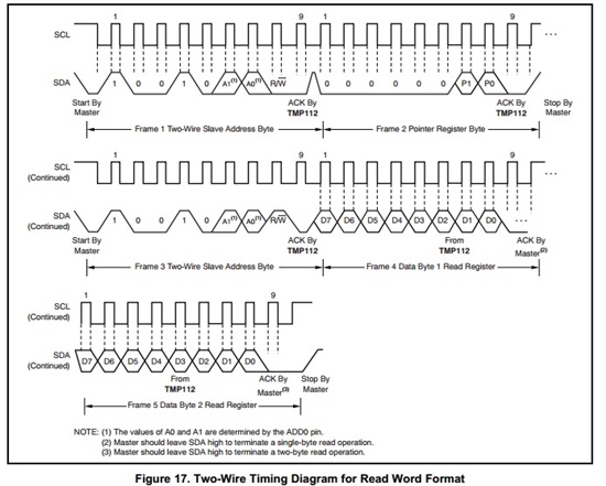
    In your  I2C_TMP112_read() function after you are sending the START condition does the line  "while (!(IFG2 & UCB0RXIFG)); "  include - (Sending Slave Address + Write) + Pointer Address + (Slave Address+read) + Data Byte 1 + data Byte 2 ?? Along with the corresponding ACKnowledgements?  In other words does the above while statement include the following:

    If you are not sure, can you probe an oscilloscope on the SCL and SDA lines to check for the above wave forms?

    Best Regards, 

    Abhi Muppiri

    Applications Engineer

    AIP- Sensing Products

    Texas Instruments


  • I just wanted to let you know, how I got the communication working for me on the MSP430G2553 at 8MHz DCO clock.

    void initClock()
    {
    BCSCTL1 = CALBC1_8MHZ;              // Set DCO to 8 MHz
    DCOCTL = CALDCO_8MHZ;               // MCLK = SMCLK = 8MHz
    }

    void initI2C()
    {
    P1SEL |= BIT6 + BIT7;                                                              // Assign I2C pins to USCI_B0
    P1SEL2 |= BIT6 + BIT7;                                                            // Assign I2C pins to USCI_B0

    UCB0CTL1 |= UCSWRST;                                                      // Enable SW reset
    UCB0CTL0 = UCMST + UCMODE_3 + UCSYNC;              // I2C Master, I2C Mode, synchronous mode
    UCB0CTL1 = UCSSEL_2 + UCSWRST;                              // Use SMCLK, keep SW reset
    UCB0BR0 = 80;                                                                         // fSCL = SMCLK/80 = ~100kHz
    UCB0BR1 = 0;
    UCB0I2CSA = 0x48;                                                                  // Set slave address (TMP112)
    UCB0CTL1 &= ~UCSWRST;                                                   // Clear SW reset, resume operation
    }

    uint16_t I2C_TMP112_read()
    {
    uint16_t temperature = 0;
    UCB0CTL1 |= UCTR + UCTXSTT;         // Master Transmit Mode, send start condition
    while (!(IFG2 & UCB0TXIFG));                // while TX buffer not ready
    UCB0TXBUF = 0x00;                                // set address pointer register to temperature register
    UCB0CTL1 |= UCTXSTT;                        // repeated Start Condition
    UCB0CTL1 &= ~UCTR;                           // Master Receive Mode
    while (!(IFG2 & UCB0RXIFG));                // Loop until I2C STT is cleared, slave acknowledge was received and RXBUFFER is ready
    temperature |= UCB0RXBUF >> 4;
    while (!(IFG2 & UCB0RXIFG));                // Loop until RXBUFFER ready
    temperature |= UCB0RXBUF << 4;
    UCB0CTL1 |= UCTXSTP;

    return temperature;
    }

    There is no need to send the address pointer with every temperature read command, but I left it in there just to be sure.

  • Hello Sebastian,

    Glad to know that you are able to communicate with TMP112 and Thanks for posting ypur findings in forums.

    There is no need to send the address pointer as long as the host know which register its reading. For example upon reset, Pointer address alwats points to address 0x00 which is the Temperature register. So if you are just concerned about reading temperature all you need to send is the I2C slave address with an intention to Read.

    Regards,

    Abhi