This thread has been locked.

If you have a related question, please click the "Ask a related question" button in the top right corner. The newly created question will be automatically linked to this question.

Need precisions concerning inductance measurement process and resolution

Hello all,

I’m currently evaluating LDC1000 for a coil inductance variation measurement application (we are currently waiting for the EVM shipping). I have carefully read the datasheet but I have not been able to completely understand

  • the internal process used by the LDC1000 to measure inductance
  • how to express the resolution on the inductance measurement

As far as I understand the datasheet the inductance measurement process necessarily uses two counters: one is connected to the oscillator and the other to the reference clock. The first one count oscillator pulsations while the second one measure the time elapsed.

First, I’m not sure about the role played by the ResponseTime register. Does it set the number of oscillator periods or the number of reference periods to count?

Secondly, I’m also wondering about the meaning of the 1/3 factor in the derivation formula. Does it means that the real counting frequency is fext * 3 for the reference counter?

Concerning the resolution, I don’t understand in what extend 24 bit announced in datasheet are defining the resolution. If the inductance measurement is based on averaging the oscillating frequency by counting the number of periods that occurs during a known time, the 24 bits only avoid counter saturation during that time. In this case the resolution on frequency measurement (and so on inductance measurement) is set by the speed at which counters operate and not by the size of the counter (I would say it is different from ADC resolution): the faster the counter are, the smaller the minimum dT the circuit can measure is. Furthermore, the resolution must also take in account the averaging process.

Many thanks for giving any precisions or opinion on that topic

Regards

  • Hello,

    I am sorry that we cannot disclose IP of the chip on this forum.

    Regarding the resolution: the lower the frequency - the higher ENOB you will get, up to 24 bits of resolution.

  • Hello Evgeny,

    I had not thought about the issues of unveiling IP  on a public forum.

    Anyway I hope you can help me in another manner. I was asking all these precisions because to estimate if the LDC1000 could match my requirements in a very small coil inductance variation measurement application.The targeted inductance coil for the system is approximately 150nH.

    I have made some trial to evaluate the module and there are some behaviors that I don't understand :

    • It was impossible for the LDC1000 to oscillate and measure properly with a LC tank made of this coil and any value of C i tried (selected in order to ensure resonance frequency between 5KHz and 5MHz). The only way to start oscillations was to add an inductance in serial with the coil. Do you have any idea to explain that? Maybe an issue with Rp... 
    • With a 22uH in serial with the 150nH coil and a 100pF capacitor, the system work properly and oscillate at approximately at 3,4MHz (configuration close from the demo LC tank). I have progressively increased the value of C to reduce the oscillation frequency and improve resolution.  It worked properly for 250pF, 470pF and 750pF, for 1nH it works with huge noise ( > 30uH) and for higher values the chip just not detect oscillations.  Do you have any idea of whats can goes wrong? Maybe there are additional constraints/ guidelines for LC tank design that I missed (I only take in account the resonance frequency) ?

    Many thanks for your help

  • Hi,

    Yes, there is a limitation on Rp values which LDC can drive. Please refer to DS p. 5 for limitation and p9 how to calculate it.

  • Hi,

    Thanks for the precisions

    I'm going to redesign my LC thank taking in account both constraints.

    Regards

  • I don't think any of us designers out here need to know the detailed IP within the chip, but the scant information on the datasheet is frankly offensive. 

    As designers we need to know whether inputA and inputB are symmetrical , or is one lower impedance than the other?.    Is the internal circuitry similar to that of the crystal pins on a microprocessor?

    Any highly accurate design will need to have faraday shielding which introduces common mode capacitance to ground, should this capacitance be preferably  more on pin than the other? Can the resonating capacitor be centre-tapped at ground potential? Is it necessary to have a DC path between A and B? 

    Just a bit of a block diagram at the inputs is all we need, and what we are looking at on the other side of the pin, (is it a gate , or an emitter or a drain?). 

    Then we can explore possibly interesting resonant topologies using tapped inductors or tapped capacitors or transformers.

  • Evgeny Fomin said:

    Hi,

    Yes, there is a limitation on Rp values which LDC can drive. Please refer to DS p. 5 for limitation and p9 how to calculate it.


    Hi Evgeny,

    My small value of target inductance (150nH) pulls Rp lower and prevent me to design low frequency LC tank

    Does it make sense to add a resistance in parallel of the LC tank to increase its RP value?

    Regards.

  • Hi , 

    This type of sensor will always work best with a larger inductance in your measuring coil.

    Basically the sense coil and the target behave as a transformer ,  so for example ,

    • 10 turns on the sense coil is the "secondary"
    • a single short circuited turn is the "primary" , with some resistance Rs

    Because of transformer action, the resistance seen at the secondary is 100 times (= n2) that of the short circuited turn.

    The Q of the resonant circuit  transforms parallel R to series R ,  in rough terms the ratio Rp/Rs = Q2  , so with a Q of 10 you get a transformation ratio of 100, so for example a 1ohm series loop resistance is transformed to 100ohm series resistance by the turns ratio. and then converted to a 10kohm parallel resistance by the Q. 

    The problem with  using lower inductances is two fold

    • The effective transformer ratio is less
    • and the Q factor generally drops (as lead resistance and capacitor ESR become comparable to the reactive impedance)

    If you desperately need to use the 150nH , then you need to operate at the highest possible frequency (to get best Q) and then use some impedance matching technique, there are two that might work, offered as examples:

    1. Use a transformer , so with a 4:1 transformer ratio , the Rp value will increase  by 16 times, and maybe a little more as the Q will improve, but the transformer will need to be 10x physically larger than your sense coil. And the parasitics of the transformer will limit the sensitivity. Maybe 10:1 would be needed?.
    2. Use a matching network :, essentially make a "tapped transformer" using capacitors. First put say 150nF (low ESR) across the 150nH, this resonates at 1MHz, with Z=1ohm  then connect a 10nF capacitor in series with the resonant network  to connect to inputA and inputB pins.  This network will look like 2.5uH // 10nF to the LDC , and the effective Rp will be ~ 200 times higher . The big problem is the oscillator in the LDC front end will probably not oscillate with this network, and may need a high value resistor or high value inductor across the input terminals.
    3. Put a piece of ferrite behind your coil, this increases L, and additionaly can be used to direct the field lines to your target

    These links might give a better appreciation of resonant circuits:

    http://www.qsl.net/va3iul/Impedance_Matching/Impedance_Matching.pdf

    http://www.ece.ucsb.edu/Faculty/rodwell/Classes/ece218b/notes/Resonators.pdf

    But summing up , if you want to use ~150nH inductor you really need a different sensor system operating at 10MHz or more.  From my perspective, the LDC approach is good,  it operates at reasonable frequencies and requires sensible inductance values,  (compared to normal inductive probes at 20kHz that require fiddly coils with thousands of turns of really fine wire)  

    Hope this helps, BobT

  • Ok , 

    I've run some sims , using "Simetrix". 

    The tapped capacitor approach only works if you can tune the frequency of a larger tank to match that of  the sense coil and it's capacitor, which would be impractical if the sensor coil inductance changed with target position (and that's expected with this application)

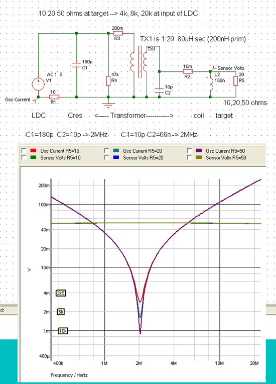
    The transformer approach requires transformers with low parasitics ,  off the shelf current transformers are optimised for low inductance and low ESR and are likely candidates. So for example search for "current transformer" at your local vendor, and look for ratios of 20:1 or less and inductance ~ 100uH .  a typical 5mm sized current transformer might be 20:1 with 80uH on secondary (equiv to 200nH on primary) with a VT product of 10V.uS  (This transformer is perhaps a bit low on primary inductance, ideally the impedance of the transformer magnetising inductance would be ~ 5 to 10 times that of your load impedance, but difficult to get 10:1 ratio in standard HF pulse transformers)

    for example : http://au.mouser.com/Power/Transformers/Current-Transformers/_/N-8u9qq?P=1z0wrguZ1yzv4q7Z1z0wpemZ1z0wfk1 

    The simulation results look like the following:

    So V1 is a  1v AC source, and R1 is a current sense, this represents the oscillator inside the LDC , it functions as a  GDO , so at the operating frequency of 2MHz, the current will be a minimum of 1mV across 10ohm , so Rp is simply 1v/100mV * 10ohm = 10k, I have tagged 10k, 5k, 2k5 for ease of reference.

    You resonant the circuit with C1 or C2 (or both) It's more practical to resonant on the secondary with 180p.

    TX1 , along with parasites R3 , R4, (and residual C1 or C2) is the transformer (R4 is a guess at the core loss, it will be temperature dependant, and a potential archilles heel) 

    L2 is your 150nH coil with some parasitic R2 . It is connected to the single turn primary with (short) , thick, closely spaced tracks to minimise ESR and ESL.

    For the simulation, R5 , the "target",  is stepped at 10R, 20R and 50R , with the resultant theoretical values of Rp being 4k,8k,20k at the LDC,  from the dip curves we see that the "real" values of Rp are a bit lower , due to parasitic effects. 

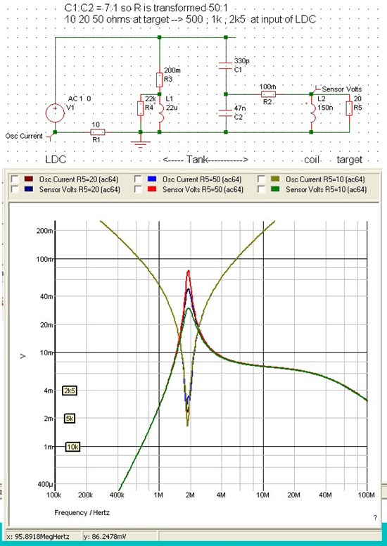
    For comparison I have simulated the capacitor tapped approach below: It is extremely sensitive to getting the L1 C1 tank resonated at the same frequency with the C2 L2 tank , and it's necessary to damp both tanks (by tweaking R4 and R2) to get an overlap. I have used 7:1 capacitor ratio for 50:1 impedance transform , and you can see the amount of change (i.e. the size of the dip) you get at the LDC is much less than the transformer approach. 

    I would have to say the tapped C approach is probably impractical in this case.

    Hope this helps , BobT

  • Hello,

    No, extra R in parallel will only further reduce the Rp of the circuit, making things worse.

  • Hello Bob,

    Thank you very much for your elaborate analysis!

    The only thing which I'd like to add is that one has to be careful with the transformer ratio. Transformer will multiply everything coming from that node! We suggest to choose the minimum ratio, at which the system starts working properly.

  • Hello Bob,

    Sorry for not answering sooner, I've missed your two last posts...

    Thank you for the time you've spend on that question and for your very elaborated analysis and proposals.

    The transformer approach seems very promising, and I hope it will enable us to use LDC1000.

    I'll get back to give a feedback after making some experiments.

    Many thanks again

    Timothé