This thread has been locked.

If you have a related question, please click the "Ask a related question" button in the top right corner. The newly created question will be automatically linked to this question.

Stepper motor digital encoder

Other Parts Discussed in Thread: LDC1000EVM, TS3A5017

Hi there,

I'm looking to build a general purpose open source stepper motor digital encoder from the LDC1000 for a Kickstarter project. Steppers typically have 200 steps/rev, however many people run steppers at up to 16x micro-stepping, giving 3200 steps/rev. I'd like to sense these steps to ensure the stepper motor moved correctly.

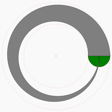
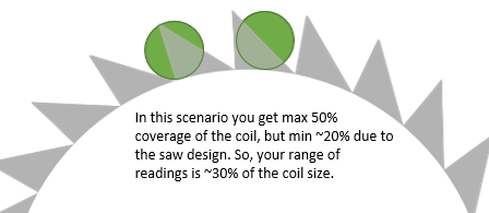
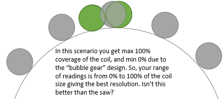
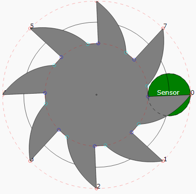
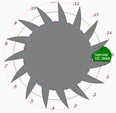
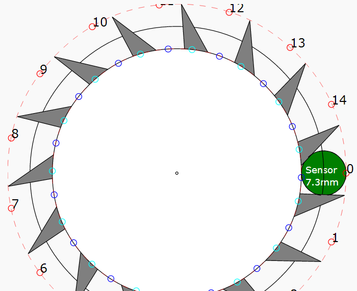
The thought is to go with a gear counting style application or perhaps the swirl measurement with 2 LDCs. I'd rather keep cost down and do gear counting so I only need one LDC. I can print a conductive ink gear with high resolution to create 3200 "gears" at the outside diameter of a plastic circle that would mount to the stepper motor axis. The diameter of the printed conductive ink circle would be at it's widest 42mm. I could perhaps make the "gears" be about 1mm in length and put them as far out on the circle as possible, i.e. at 41mm diameter stretching out to the 42mm in diameter. The circumference of that circle is roughly 132mm so the "gears" would have to be 20 microns of conductive ink, 20 microns of no ink, etc. Is it feasible to detect gears this small? The datasheet and marketing materials refer to detecting sub-micron resolution so it seems I'm well above that at 20 microns.

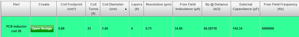
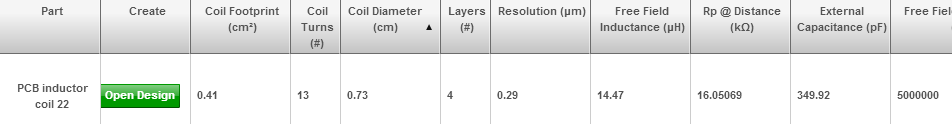
A further question is, what size coil on a PCB would be needed to detect the 20 micron wide gears and their movement? From reading the datasheet and forum it seems like a coil the size of the circle would be needed, but if you are counting gears is it a different formula? I could do a coil with a 42mm diameter if needed but it would make for a large final package. Or, could I do a much smaller coil, say a 10mm one, since I'm detecting gears with motion parallel to the coil rather than detecting distance? Would a 1 layer PCB coil be good enough as well? 

Thanks,
John

  • Hello John,

    To resolve 20um gear teeth you will need a 20um dia coil, which is not practical.

    Better solution in this case is the rotary slider, or "swirl" shape. We are working on rotary reference design with 0.1° angular accuracy - this will be ideal for your application. Please keep in touch, once it's released you can reuse it.

  • Hi Evgeny,

    I built a swirl calculator that is available for anyone to use and modify. I think this could help the whole community here try to design their swirl patterns. Please feel free to branch the code on JSFiddle.

    http://jsfiddle.net/jlauer/SBfy6/embedded/result/

    Here is the swirl I think I could use. It's a 55mm diameter so it fits a Nema23 motor. The coil sensor is 14mm which is the same as the LDC1000EVM. The sensor is in green in the picture.

    The question though is, with where the swirl is over the sensor (in green) it appears that resolution is lost. If I am testing for movement and I know which direction the movement was supposed to go, should i still be able to deduce whether the stepper motor moved a step? It would seem that I should be able to detect something.

    I will mill out this swirl shape to test it, but i'm thinking there may not be enough "new" metal at each step for the inductance sensor to pick it up. Would it make more sense to gang up multiple swirls to get more metal over the sensor at each step?

  • Hello John,

    Thank you very much for your efforts! Do you mind if we add this swirl generator to FAQ?

    Regarding the resolution - indeed, then the sensor crosses over the thin to thick part, the resolution will be dismal. To address this issue we recommend using second sensor located with the offset from the 1st such that when one is in dead zone, the second one operates fine.

    To increase resolution due to higher metal change with each step we can recommend the crescent shape, as in this image: http://www.monosquare.com/products/brass-bottle-opener-crescent#.UnqCSeKmXVs

    Now there are two dead zones, but second sensor will compensate for this.

    Please also keep in mind that for high-accuracy measurement temperature compensation is likely required (see our apps note on this topic)

    I did not quite understand what you mean by  "Would it make more sense to gang up multiple swirls" - could you please elaborate? An image, perhaps?

  • By all means add the swirl calculator to the FAQ. It's for everyone and I hope folks modify it for more design shapes. All the base code is there now.

    Yes, by "ganging up multiple swirls" I did mean that crescent shape you provided a link for. I'm even thinking 2 crescent shapes.

    I can add code to the swirl generator that lets you pick a crescent shape or even a multiple shape.

    I'm trying to figure out how to do this encoder board with only one LDC1000 to keep costs down. If i have to use 2 or even 3 it kills the price point.

    Also, i don't really need to know the absolute position of the stepper motor. I only need a relative position of "did it move" or "did it not". I'm thinking this swirl shape would give me an absolute position for 90% of the shape, but that's overkill for my needs. So, i'm trying to make the shape work to use only one LDC1000 and at least know relative movement.

  • Hi John,

    In the case of figuring out relative movement you are better served with a saw.  If you need to know direction as well make it asymmetric.  To resolve 20um you will need a 20um coil only if you are using a gear.  With a saw you have the benefits of the swirl but a distributed deadzone which can be more advantageous if you design the saw such that the stepper motor never stops with partial overlap of the steep edge.

    Here's an example:

    Thanks,

  • For a relative change you will not need temp. compensation, so 3 LDCs are not required.

    What is the time frame for your project? We are going to have parts with multi-channels, with better prices per channel.

    Please keep us posted on the results, once you got your shape and had a chance to measure it!

  • Hi Charles,

    I'm thinking about your saw design more. I need to read 3200 steps around the circle, so that's 0.1 degrees. If I use the saw design you're suggesting, I'm guessing the coil sizes would be like the picture below. I'd need 2 coils offset from each other to deal with deadzones.

    In thinking about the saw, it feels like the readings on the LDC1000 would have resolution from about 30% of the coil size, so not that much range, but perhaps workable. It makes me think in your saw design I'd want to make the coil size about 50% of the height of each saw blade to get the offset coil to have 0% coverage while the main coil has 100% coverage to get the broadest set of readings on the LDC. If that's the goal of the saw design, wouldn't a "bubble gear" design work better like below?

    It sure is feeling like I'll need 2 LDCs. Evgeny, this project could be released in the next 3 months. When do the multiple channel LDC's come out?

  • Hi John,

    For the asymmetrical saw, the coil will be small enough such that there will be a position where there will be very little overlap.  The idea behind the asymmetrical saw is for single coil sensing.  The example saw is just an example; the spacing between the saw blades can be increased to accommodate larger coil sizes, the shape can be adjusted (slightly curved) to compensate for any non-linearities from physical arc movement, and the slope can be adjusted for optimal resolution for 0.1deg rotation.

    If you oversample you can determine the direction of movement from a single coil even through the deadzone by looking at the slope of the data when it changes; with the symmetrical bubble gear this will not be possible.  The asymmetrical saw increases the sensitivity of the coil to the deadzone over the swirl since the slope per degree is steeper, but the swirl has the advantage of absolute positioning and support for a larger coil.  Note that slope detection is heavily dependent on the speed at which the stepper motor moves, which has to be consistent.

    The bubble gear is an interesting idea, but, just like with the 2-coil saw, the coils must be placed as far away as possible to avoid interference.

    Where would one begin?  In all the examples, the shape is determined mostly by coil size.  Find the minimum coil size which can give you enough L for an acceptable sized cap at 5MHz and Rp within range. 

    Thanks,

  • Hi Charles,

    I'm trying to take all of your feedback on the asymmetrical saw and see what the the best layout is. I modified the Javascript SVG Swirl Calculator to now produce a saw akin to your example. I have a straight saw and a curved one. It's animated so I can see where/how the overlap works on the sensor. The calculator is now getting fairly sophisticated. Here's the results below.

    http://jsfiddle.net/jlauer/SBfy6/embedded/result/

    [I tried pasting in direct SVG code to the forum editor and it looked great, but at some point it gets wiped out and no SVG image shows. So I just uploaded some PNG's instead.]

    SVG for 8 blades curved.

    SVG for 6 blades curved.

    SVG for 4 blades curved.

    SVG for 8 blades straight.

    The questions I have are:

    1. Is my sensor too big for this saw shape? Should I reduce it's size by 20%, 50%, or so? I used the size from the evaluation model to start.
    2. What's the best number of saw blades? I feel like the 4 or 6 blade curve is best.
    3. Should I be curving the right side of the asymmetric saw? The straight line doesn't look as good.
    4. The left side of the saw is angled at 2 degrees. Is that enough?

    Before I start milling out the shape on the CNC machine using a copper PCB I want to make sure I'm not wasting my time on the right ratios. I'm thinking you would have the best feedback on what will give the best readings.

    Thanks,

    John


  • Trying to see if an IFrame will help me embed the animations because I think they're key to helping visualize the slope of the saw design.

  • Here's the design I think I'm going to go with. It has 7 blades. The coil is a bit smaller at 10.5mm based on the Webench suggestions. It has a free field frequency of 5Mhz. The overlap of the sensor is very small between blades with a 9 degree offset added. I could add a bit more offset if needed.

    Here's the webench coil.

    Some other ideas, based on Charles' original saw image, with the 10.5mm coil don't seem to be as nice, for example if I jump to 15 blades it feels like I won't have enough coverage of the sensor or too much overlap between blades.

  • 1. l would reduce the size as much as possible due to the relatively tight 0.1 relative angle detection requirement.

    2. having more saw blades and a smaller coil size will be best.  The reason for this is twofold: greater sensitivity to angle detection and fewer samples to detect deadzone since

    delta Area Overlap / delta Time is greater in magnitude, the area changed per 0.1 degree is larger than for fewer saw blades.  However you have to balance this out with the maximum overlap since the tradeoff is a saw blade that will maximally overlap the coil less; e.g. 8 blades straight

    3. The overlap should be exponential to counteract the nonlinearity.  However, this depends on a few things: whether you will use Rp or L (I would use L due to greater robustness against wobbling), how optimum the Rp range setting is for your coil, and whether or not you hollow out the center to avoid fringing field offset.

    I would stick to linear for now.  When you have some data, curve fit it to work on a more optimal shape.  There are too many parameters to avoid approaching this phenomenologically (but you will likely end up curving slightly left instead of right).

    4. yes

  • Hi John,

    Let me say fantastic work so far.  I've separated my reply in two posts. 

    The 7 blade is more attractive but I would:

    1.  space out the blades enough for there to be very little overlap.  Having overlap from two blades decreases your resolution.  This means reducing the size of the blades / increasing degree offset.

    2. Hollow out the center to avoid a fringing field offset.

    Thanks,

  • Ok, I updated my design based on your feedback. The goals were:

    http://jsfiddle.net/jlauer/SBfy6/embedded/result/

    1. I went with straight blades per your suggestion on reading the data.
    2. Increase the amount of blades. I have 15 now.
    3. Reduce the overlap to barely be there from blade to blade. In the screenshot you can see the slight overlap. Is this still too much? If the blade gets close to the coil, but not over it, I assume it would still detect it. I went with an 11 degree offset to get this design. I could go 10 degrees for no visible overlap in the design.
    4. Reduce the coil size as small as I can go. I took the smallest coil I could find in Webench which was 7.3mm 4 layer.
    5. Cut out the middle of the saw for no fringing effect.

    The coil from Webench is:

    Questions:

    1. Should I get a real wound coil instead of using a PCB coil to go even smaller?
    2. Is 15 blades going to make me happier? Should I go to 20, 25, 30? Obviously would need smaller coil.
    3. Should I reduce my overlap more from the screenshot?
    Thanks so much. This is quite a process to get a good design.
  • 1. only if that is cost-effective

    2-3. You should increase the overlap per blade, which will reduce the number of blades.  The portion of the blade touching the rim of the inner white circle should be roughly the diameter of the sensor.  Reason: the sensor cannot differentiate in the current configuration for the 0.1deg angle steps when the blade is fully overlapped (since it is fully overlapped for a range of angles); you only want a full overlap in a specific 0.1degree resolution angle.  In other words, from a full overlap position, any 0.1deg change will result in partial overlap.

  • Ok, the design I went with for now as part of the continued experimentation is below. The reason I did this design was I wanted the widest resolution I could get at each stepper motor step. I only want relative positions, so this design seemed to bring the widest range. You can tweak the design at

    http://jsfiddle.net/jlauer/SBfy6/embedded/result/

    I milled out the shape on a PCB so I could put it on a stepper motor to do some data testing.

    After mounting it and milling out some acrylic to hold the two inductors in an offset position I got this.

    Here is the PCB in its final position for testing.

    I am getting pretty good data from swapping between two PCB inductors really fast using TI's TS3A5017. I have to run the LDC1000 at 2V to not go over the limits of the SP4T analog switch. I do find that I get some anomalies on the proximity data. Not sure if those are bad for the LDC1000, but I know I can toss out the weird data to not throw off averages. Toggling between the 2 inductors every 10ms or so gives a pretty good way to use a steep curve of data from one inductor while the other inductor is giving fairly flat data.

    Here is some oscilloscope output to see the resonance from the LDC1000 through each of the 2 inductors as I swap between the two. The SP4T isn't perfect at turning off each channel as seen here, but it doesn't seem to mess too much with the data above.

    So, the questions here are:

    1. Do you think this will alleviate temperature concerns by dividing the 2 inductor values into each other's data? I've already seen a lot of temperature fluctuation because stepper motors get hot. Should I perhaps even divide inductance values as well as proximity values into each other to get a more accurate final number for each step?

    2. Are the proximity data anomalies as seen above as the spikes ok for the LDC1000? I only get those when I use two inductors.

    3. In the data above I am switching both leads from the inductors on the SP4T, each on a different channel. This makes me think though that the current on the inductor, when both leads are switched at the same time, has nowhere to go other than just dissipate from resistance. However, when I leave one set of leads from each inductor all connected direct into the LDC1000 I get data that is less flat at each step. Does it not really matter and it's whatever gives me nicer data?

    Thanks for all the help here. You guys have been great.

    -John

  • Hi John,

    This is great documentation, programming, and design! 

    1. As long as the inductors are localized enough to avoid temperature gradients dividing the data would help to avoid fluctuations.  We would recommend using just inductance values.

    2. They might be due to coupling between the two inductors.  You can try spacing apart the oscillating frequency > 800kHz by sizing the inductors differently.

    3.  (From what I can tell from the pictures you're switching two LC tanks, and not just L)  Yes it would dissipate from parasitic resistance.   I would discard the first few inductance measurements after switching.  I don't understand what you mean by leaving one set of leads connected.  Can you elaborate?

    Thanks!