This thread has been locked.

If you have a related question, please click the "Ask a related question" button in the top right corner. The newly created question will be automatically linked to this question.

Usage LDC1000EVM in custom application

Hello,

I am using a LDC1000 in a custom application (broke USB part from EVM apart, soldered connector) and have similar issues as readable in this thread: http://e2e.ti.com/support/data_converters/inductive-sensing/f/938/p/292151/1018937.aspx#1018937

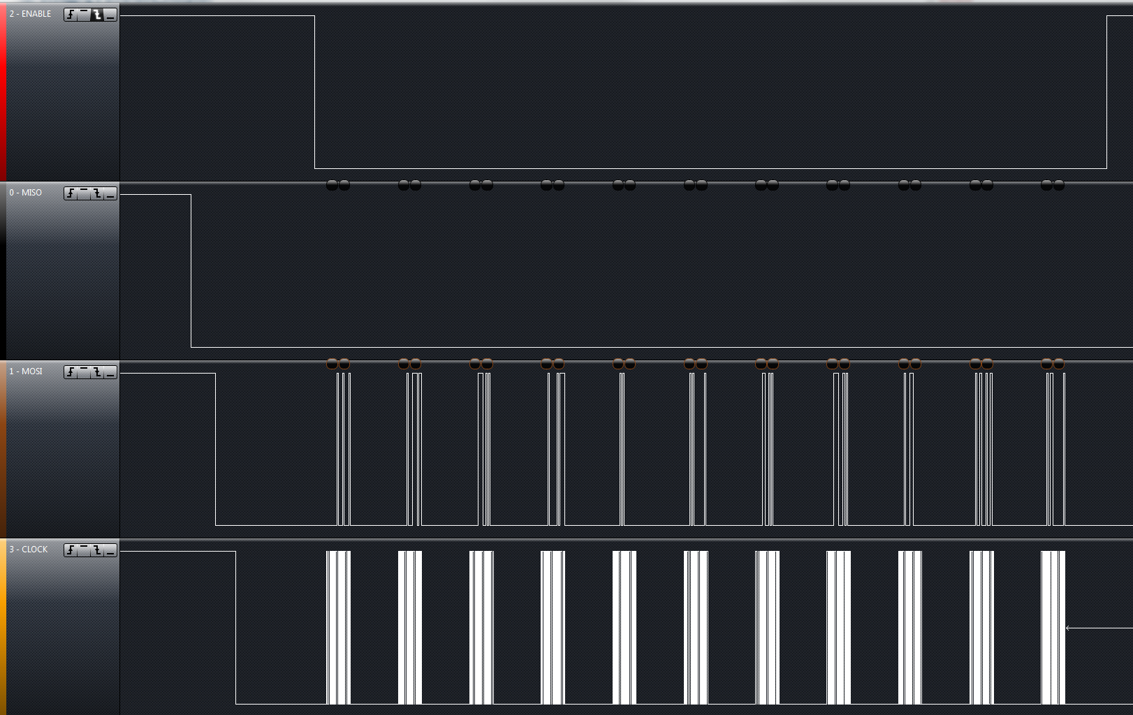
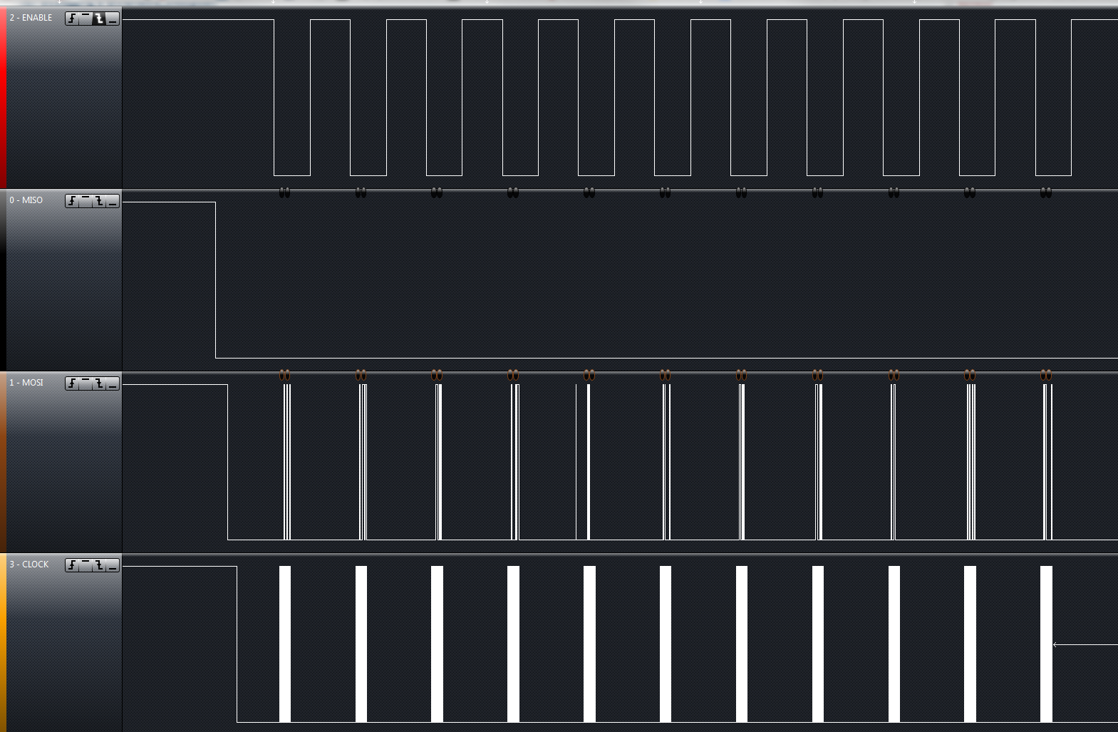
Sadly the solution does not fit in my case. I made sure, I have VIO on 3V, the same digital supply voltage my STM32 gets. Also I can see all communication works fine except the SDO line (just stays on GND).

I supplied a 8MHz LDCKL and also tried a 2MHz clock.
Nothing changes.
Here is my init sequence:

ldc1000_write_cmd(LDC1000_CMD_RPMAX,		TEST_RPMAX_INIT);
ldc1000_write_cmd(LDC1000_CMD_RPMIN,		TEST_RPMIN_INIT);
ldc1000_write_cmd(LDC1000_CMD_SENSORFREQ,	0x94);
ldc1000_write_cmd(LDC1000_CMD_LDCCONFIG,	0x17);
ldc1000_write_cmd(LDC1000_CMD_CLKCONFIG,	0x00);
ldc1000_write_cmd(LDC1000_CMD_INTCONFIG,	0x02);
ldc1000_write_cmd(LDC1000_CMD_THRESHILSB,	0x50);
ldc1000_write_cmd(LDC1000_CMD_THRESHIMSB,	0x14);
ldc1000_write_cmd(LDC1000_CMD_THRESLOLSB,	0xC0);
ldc1000_write_cmd(LDC1000_CMD_THRESLOMSB,	0x12);
ldc1000_write_cmd(LDC1000_CMD_PWRCONFIG,	0x01);


Thanks for any advice, I appreciate it.
Stefan

  • OK, I found out something.

    I had to change the init function in order to supply a valid start and stop condition around every single command.
    First off I had generated a start condition, supplied all my commands (init sequence) and generated a stop condition.

    I attached screenshots of the prior and after situations. Please forgive my I2C speak

     ...

  • Hi Stefan,

    One easy way to determine if your signals are correct is to connect your logic analyzer to the EVM, which outputs the correct signals.

    It seems to me that perhaps there is a misconfiguration of your microcontroller SPI registers.  I would validate that first to be sure that the microcontroller is not intentionally holding MISO low, and that the idle state of SCLK is high (it does not appear to be so).

    Next, I would validate that the rise and fall times are valid on a scope.

    Thanks,

  • Hey Charles,

    thanks for your quick answer.
    Actually I got it running, when I just used the setup shown in the second picture.
    All lines idle state should be HIGH, right?

    I may have to tune on this, that's true. It looks strange.

    Rise and fall times seem to be in range, as I am able to gather valid output data.

    Actually I saw that over time the signal values shift. In my case it was a drop of 100 units (prox raw data) over a time of 10 Minutes. How could I compensate without beeing able to use a second coil?

    Regards
    Stefan

  • Not all lines have to be idle high SDI (data in) does not have to be idle high.

    The shift will be fixed for future products.  In the meantime we recommend using frequency counter data as it is affected less by noise in the INA/INB line.

    Thanks,

  • Hey Charles,

    thanks for the reply.
    I now used frequency data as you recomended, it is very linear and stable. There's one thing though, its resolution is not suitable for my application. Can you recommend how to improve this? I am curious since this is a 24Bit register but my values range from 1k to 2k.
    I opened another thread for this.

    Thanks for your suggestions.

  • Hi,

    LDC1000 use counter to measure frequency, if the data rate is high, we can only get less counts in every sample, you can use large inductance and high Q coil, then we may get more counts. Or you can use moving average filter after you get the data.

    Thank you.