This thread has been locked.

If you have a related question, please click the "Ask a related question" button in the top right corner. The newly created question will be automatically linked to this question.

LDC1000 in Rotary Application

I have a customer who is using the LDC1000 in a linear sensing application. They would like to use it in a rotary application. Currently, they have a triangle to measure linear displacement, but a rotary may be more deterministic.

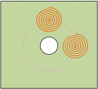
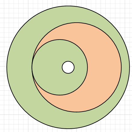
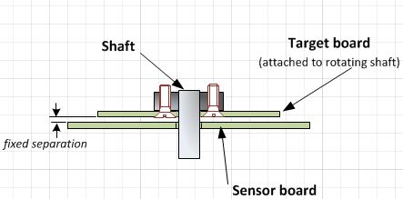
Is there  an example of how to make the rotary wheel – as if you were going to measure motor movement?

  • Hi John,

    There a many different types of rotation applications. For example, if you need to measure a partial rotation (for example, only 270 degrees of rotation), then a single coil can be used with a target rotated around a pivot point. Note that it is important to control the Z height.

    For a full rotation, 2 or more coils are needed. A good implementation using 2 coils with 90 degrees apart on a sensor board, as shown below:

    We then have a rotating target for the sensor to detect. A good target shape (where the orange is copper) is:

    The target would be attached to the rotating component while the sensor board would be fixed. A side view would be:

    It is important to maintain a fixed separation. To determine the angle, measure the response of the two coils and use the Arctangent function to determine the angle.

    Regards,

    ChrisO