This thread has been locked.

If you have a related question, please click the "Ask a related question" button in the top right corner. The newly created question will be automatically linked to this question.

custom coil noise and inductance resolution

Hi,

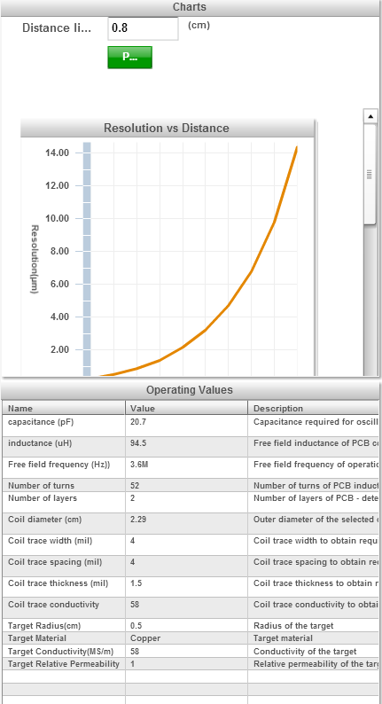
I'm using a custom coil to test some tiny movement. The coil is designed from the Webench:

http://webench.ti.com/webench5/ldc/index.cgi?c=20.67&l=94.53&nl=2&nt=52&f=3600000&cres=14.25&cd=2.29&d=0.8&res=20&td=1&tm=0#

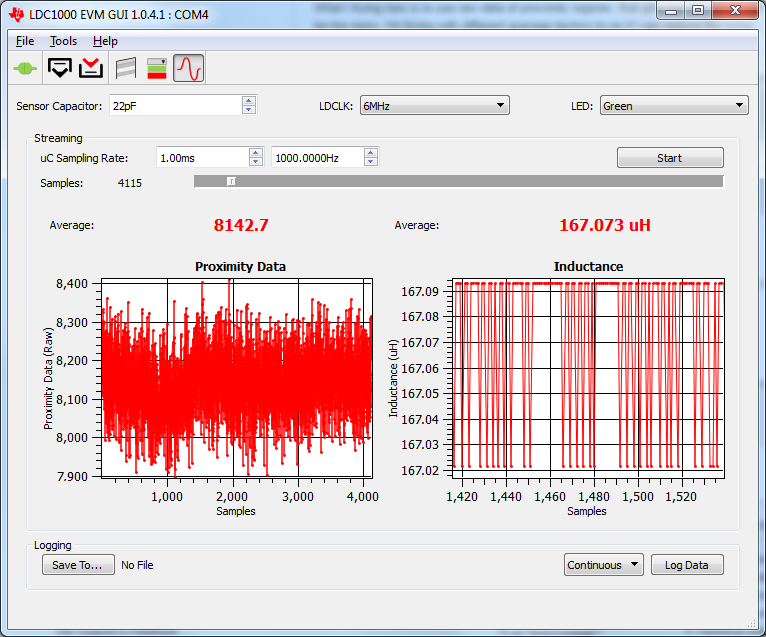
The parallel capacitor is 22pF and I change the GUI settings as following. The resonance frequency is 30.1MHz. I didn't change the filter capacitor, is that OK? 

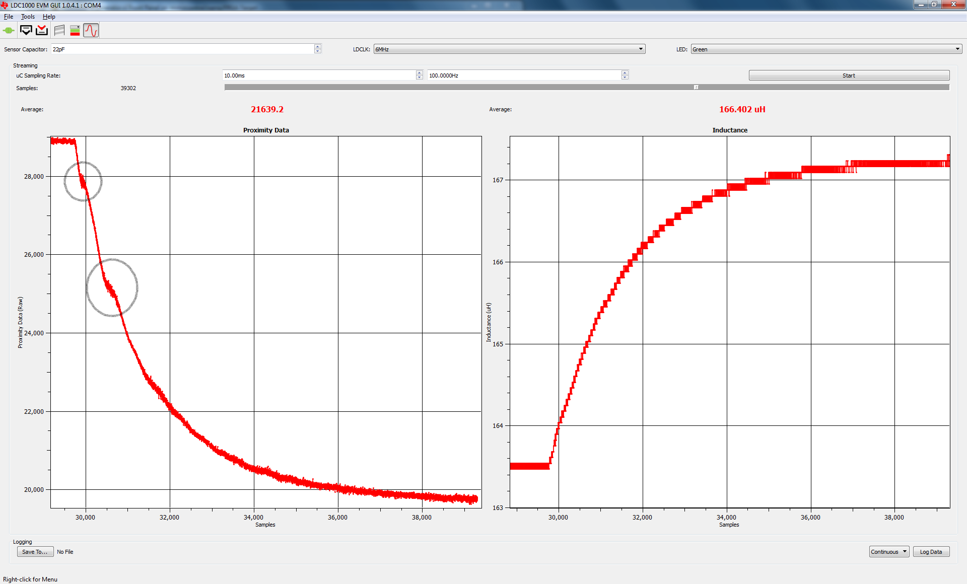
And this is the output when a small target is placed near the coil but doesn't move. Is the noise too large? How can I do to achieve a smaller noise?

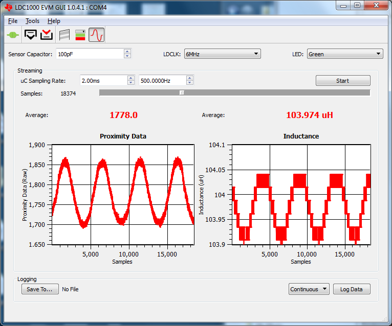
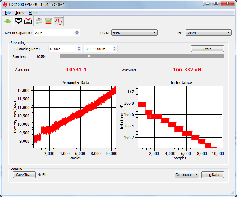
This is the reading when the target moving close to the coil in a constant speed (1000Hz step signal). Seems the resolution of the inductance reading is too low. Is there anything I forgot about the inductance setting?

Thanks,

Jiaqi

  • I also did a test that the target slowly moves away from the coil in a constant speed. I think the shape of output is right but have no idea about these two inconsistent parts in the circle. Can someone give any suggestions about what is this?

  • Hello Jiaqi,

    I assume the 30MHz is the Self-resonance frequency of the sensor, not the operating frequency. Note that I cannot access the sensor design from the provided link. I would also recommend a sensor design with a larger capacitor value than 22pf; it is possible parasitic capacitances could be the source of the issue you are encountering.

    Regards,

    ChrisO

  • Hi Chris,

    Thanks for the reply. This is the parameter of my coil. I use a 22pF capacitor just because we don't have 20.7 in lab. The 30MHz frequency is from the impedance analyzer. So do I need to change a bigger parasitic capacitor? 

    Thanks,

    Jiaqi

  • Hello Jiaqi,

    Thank you for the information. We don't refer to the sensor capacitor as a parasitic capacitor. The sensor capacitor is used with the inductor to set the operating frequency. So, your sensor has an L of 94.5uH and a C of 20.7pF, which operates at 3.6MHz. One concern with a small value sensor capacitor is that there is always some parasitic capacitance present from any other physical objects nearby. It does not take much to have 1pF of parasitic capacitance, but a 1pF change in the capacitance will shift the sensor frequency by 100kHz, which is equivalent to a shift in the inductance of 5.6uH.

    I generally recommend sensors with a C of at least 50pF. You can change the sensor capacitor to 100pF, and you will have a sensor frequency of ~1.6MHz.

  • Hi Chris,

    Thanks for your quick reply. But I'm still a little confused about the capacitance in the WEBENCH. Is that 20.7pF the recommended capacitor for an ideal sensor?  Because I have 4 different coil designs, could you please give me some suggestions on how to select the capacitor?

    Thanks,

    Jiaqi

  • Hello Jiaqi,

    The 20.7pF is the provided value for the sensor capacitor, but it can be changed to a different value. Using a larger value capacitor will result in a lower frequency sensor. For the LDC1000/1041/1051, the result will be a lower sample rate. If necessary, you can use a lower response time setting if the lower sample rate is not sufficient for your application.

    The main restriction on the sensor frequency should be 5kHz <= fsensor <= 5MHz.

    The sensor frequency is determined by fsensor = 1/(2*PI*sqrt(L*C)).

    The sample rate is SR = 0.3333 * RESPONSE_TIME / fsensor

    I recommend using a capacitor value greater than 100pF to reduce potential parasitic capacitance effects.  

  • Hi Chris,

    Thanks so much for the detailed reply. I'll try a large capacitor and let you know if it works,

    Thanks,

    Jiaqi

  • Hi Chris,

    I changed the capacitor to 100pF. Seems the noise is better but the inductance resolution is still low.  What could be the reason for this problem?

    Cheers,

    Jiaqi

  • Hi Jiaqi,

    The effective inductance measurement resolution is based on several factors:

    1) the TBCLK/XTALIN frequency - the higher it is, the better. The max for this parameter is 8MHz; note that the EVM only uses 6MHz due to USB interface timing restrictions.

    2) the sensor frequency - the lower the sensor frequency, the more resolution available. You can increase the sensor cap to 1000pF and improve the resolution by ~3x compared to the 100pF sensor.

    3) the response time register setting - the larger this is, the more accurate the measurement, although at the expense of conversion time.

    4) the actual change in sensor inductance due to target motion. A larger sensor or positioning the target closer will result in a larger shift in inductance, also providing more resolution.

    Regards,

    Chris O  

  • Hi Jiaqi,

    One additional note - you can also average multiple conversion results to improve the resolution further. The resolution improvement will be the SQRT(N), where N is the number of averages. If you average 16measurements, you will have 4x the resolution.

    Regards,

    ChrisO

  • We have seen similar behaviour as shown in the circles with standard coil.

    Search for the posts:

    First samples in datablock with Command : "06" with Firmware version 0.3.0.0

    LDC proximity reading confusion

    Thanks for sharing your testresults.. Sorry I do not have an answer to why the behaviour occurs.

    Regards Torgeir

  • Hi Chris,

    I tried larger capacitors but the results are even worse. Is that because my target is too small ( 0.5 cm*0.5 cm 1CM away from the coil)? Also I didn't find the SQRT(N). Could you please tell me where is it?


    Thanks,

    Jiaqi

  • At a distance of 1cm with a 2.2cm diameter coil, you will have reduced resolution, especially with the smaller size target that you are using. The resolution will be better with the target closer, and also with a larger target.

    The SQRT(N) is the square root function.

    Regards,

    ChrisO