This thread has been locked.

If you have a related question, please click the "Ask a related question" button in the top right corner. The newly created question will be automatically linked to this question.

LDC1000 Designing of Sensor

Other Parts Discussed in Thread: LDC1000EVM, LDC1312, LDC1612

Hi,

My customer want to detect pistons of cylinders by LDC1000.

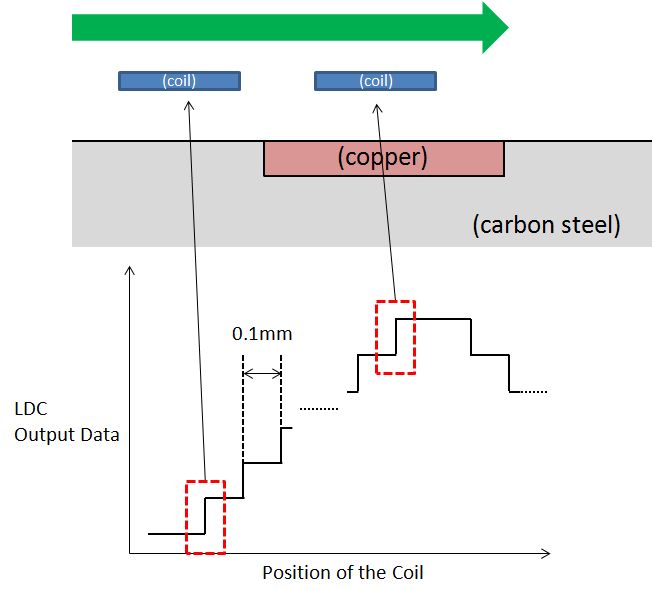
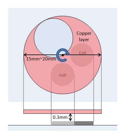
In concretely, the pattern of cylinders is detected by the sensor of coils.

I attach the figure of the condition.

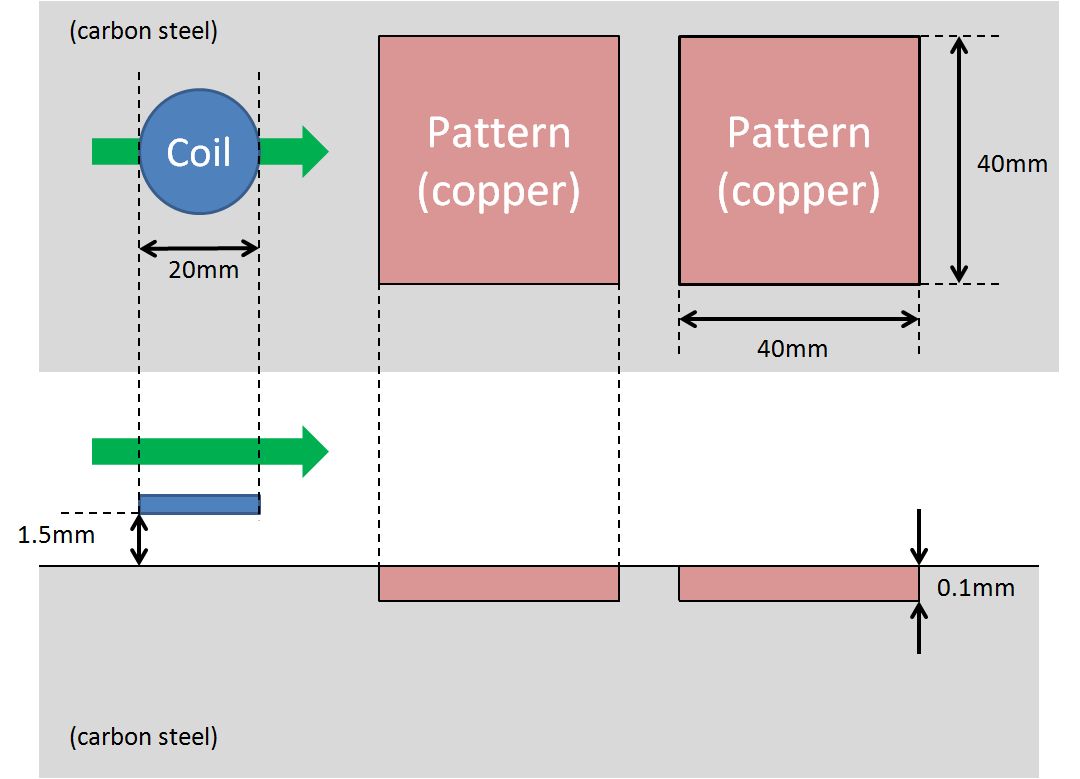
The detecting point is from beginning lap of coil and pattern to completing lap.

Could you give me advice about designing of sensor(ex. coil turns)?

Please let me know lack of information.

Thanks,

Kuramochi

  • Hello Kuramochi-san,

    Your diagram looks good. However, I would need more information to assist.

    I assume you are planning to use L measurement only. What is the desired oscillating frequency of the sensor? How many PCB layers are you planning to use?  

    Best Regards,

    Natallia Holubeva

  • Natallia-san,

    Thank you for your quick response.

    How should they decide the oscillating frequency?

    They tell me not to have the desired oscillating frequency.

    (I can't understand Fcount. Should they obtain Fcount(0x23~25) with EVM?)

    They plan to use 2 layers of the board.

    Thanks and Regards.

    Kuramochi

  • Hello Kuramochi-san,

    The oscillating frequency of the sensor is determined by the following formula: f = 1/(2*PI*SQRT(L*C)). The range is 5kHz- 5MHz, described by the D/S. All I would worry about here is to stay away from the existing frequencies in the system (for example, if you have another signal at 1MHz nearby you would not want to operate at 1MHz).

    Here is what I would recommend regarding the number of the turns in the coil: the more turns you have, the larger the inductance will be. Since the diameter is only 20mm, you want to use as many turns  as you can. Your limiting factor here is determinted by the price of PCB manufacturning. Thus, I would advise your customer to do as many turn as possible in his pricerange.

    Regarding the Fcount, please, refer to the following paragraph on the page 12 of the D/S:

    fsensor = (1/3)*(Fext/Fcount)*(Response Time)

    where Fext is the frequency of the external clock or crystal, Fcount is the value obtained from the Frequency Counter Data register(address 0x23,0x24,0x25), and Response Time is the programmed response time (see LDC configuration register, address 0x04).

    Based on the above, you know your sensor frequency (set by L and C components). You know your external frequency (set by the oscillator). You also know your response time since you set it. Thus, you can either calculate Fcount or read it from the registers.

    Best Regards,

    Natallia Holubeva


  • Natallia-san,

    Thank you for your advice.

    I tell it to my customer.

    Is it difficult to show the minimum number of the turns in the coil?

    ************************

    The coil moves at 1m/s.

    Is there the point that they should take care?

    Best Regards,

    Kuramochi

  • Hello Kuramochi-san,

    Let me give you an example for your geometry: with 4milx4mil (spacing between traces and width of trace), 2 layers, and 6 turns per layer you get ~ 5.437 uH of inductance. 5uH inductance is border line sufficient to satisfy LDC1000 constrains (f sensor range and Rp range).  If you can have more turns, your inductance will go up, which gives you more freedom of selecting the capacitor. We generally recommend >5uH inductance (please note that it is possible to add a descrete inductor in series, but the % change will be minimized then).

    Best Regards,

    Natallia Holubeva

  • Hello-Nattalia-san,

    Thank you for your information.

    Is it correct that 4milx4mil = 0.1mmx0.1mm?

    I think that this is very small for the coil of sensor.

    And, is border line always 5uH regardless of  detecting condition?

    Thanks,

    Kuramochi

  • Kuramochi - san,

    4x4 mil refers to the width trace and space between traces of the coil. These specs you enter in Altium when you are designing the coils. The PCB coil on LDC1000EVM uses 4x4 mil specs. You can choose otherwise - I just gave you an example.

    You need to stay in the range of 2 parameters for LDC1000: Fsensor and Rp. Low inductance wont have enough parrallel resistance; thats why you need at least 5uH regardless of the test conditions.

    Best Regards,

    Natallia Holubeva

  • Natallia-san,

    Thank you for your information.

    I understood them.

    ************************

    My customer needs the resolution of ±0.1mm and linerity ±0.1mm.

    Please refer the following diagram.

    The oscillating frequency of sensor is about 100kHz.

    How should we think about the optimum inductance or number of the turns in the coil?

    Best Regards,

    Kuramochi

  • Hello Kuramochi-san,

    Again, that would depend on your fabrication constains. At 4x4 mils and 20 mm diameter, you could usea  2 layer board with 12 turns per layer as I described above. With12 turns, the total inductance would be ~19uH. Since the operating frequency is 100kHz, you would need a 133317 pF (133nF) capacitor in parallel.

    Best Regards,

    Natallia Holubeva

  • Hello Natallia-san,

    I appreciate your advice.

    I tell your example to my customer.

    Thanks and Regards,

    Kuramochi

  • Hello Kuramochi-san,

    You are always welcome. Please, let me know if you have any other questions.

    Best Regards,

    Natallia Holubeva

  • Natallia-san,

    Wishing you a happy New Year!

    I ask you the other case.

    I hope to detect angle of a rotator and to get the sin-wave(and cos-wave).

    I am thinking the following pattern for this condition.

    If you have the better idea of the pattern, please let me know.

    And, I also ask you spec of LDC1000.

    How much is ENOB of LDC1000?

    Thank and Regards,

    Kuramochi

  • Hello Kuramochi-san,

    Happy New Year to you too! Your design looks good. Regarding the LDC1000 ENOB, there would not be a straight answer since the ENOB will depend on mechanics of the system, target material composition, etc.

    Best Regards,
    Natallia Holubeva
  • Hello Natallia-san,

    Thank you for your quick response.
    I understand them.

    And I have the other question.
    What is L Resolution ?
    What does this influence?

    Thanks and Regards,
    Kuramochi
  • Hello Kuramochi-san,

    L measurement is dependent on various mechanical constrains of the system. The most influencial would be the distance between the sensor and the target. Are you using L measurent only? In this case, I would recommend using LDC1312 or LDC1612 ICs since you have 2 coils.

    Best Regards,
    Natallia Holubeva
  • Hello Nattallia-san,

    Thank you for your reply.
    I understood.

    >Are you using L measurent only?
    I haven't already decided it.
    Could you tell me that what is advantage to use each L measurement or Rp measurement?

    Thanks and Regards,
    Kuramohci
  • Hello Kuramoch-san,

    I would advise you to decide on which measurement the system will be using first. L measument is mostly used for distance detection, gear counting, spring compression. Rp measurement is used for metal composition detection. In you case, if L is sufficient, LCD1312/LDC1612 would be a better fit. Maybe you could order EVMs for each and do some testing?

    Best Regards,
    Natallia Holubeva
  • Natallia-san,

    Thank you for your support.
    I understood each advantage.
    I will use L measurement.

    And, I'm examining to use LCD1312/LDC1612.
    These IC has 2 input, but 1 ADC.
    I have been reading the datasheet of LCD1312/LDC1612.
    Please wait a moment.

    Thanks and Regards,
    Kuramochi

  • Kuramochi-san,

    Please take your time. LDC1312/LDC1612 have an internal multiplexer and thus 1 ADC. For an application with 2 coils like yours, this new IC has many advantages. The only concern is that it is an I2C device, so it will be slower than LDC1000 which uses SPI.

    Best Regards,
    Natallia Holubeva
  • Hello Natallia-san,

    I have questions.

    The maximum Channel Sample Rate is 4.08kSPS in the datasheet of LDC1612/1614 .
    If the number of using channel is 2, is this value 2.04kSPS?

    What is the unit of the response time in LDC1000?

    If it is "sec", is the maximum sample Rate 8.68kSPS?

    ⇒ 5MHz/(192*3)=8680


    Thanks and Regards,
    Kuramochi

  • Hello Kuramochi-san,

    Yes, for the LDC161x and LDC131x, the effective sample rate decreases with multiple channels; this comes from the I2C bandwidth.  

    The response time setting for the LDC1000/1041/1051 is in cycles of the sensor frequency; so for the LDC1000 family of devices the maximum sample rate is set by the 5MHz maximum sensor frequency spec (0.2us) times the 192 lowest setting for the Response time which leads to ~78ksps maximum sample rate.

    Regards,

    ChrisO


  • Hello Chris-san,

    Thank you for your answer.
    I understood.

    Thanks and Regards,
    Kuramochi
  • Hello Kuramochi-san,

    Please let us know if you have any additional questions.

    Best Regards,
    Natallia Holubeva