This thread has been locked.

If you have a related question, please click the "Ask a related question" button in the top right corner. The newly created question will be automatically linked to this question.

Stabilizing Rp measurement

Hello

I'm using the LDC1000 for metal composition measurement therefore a stable measurement of Rp is required. My LC-tank oscillates at around 3,6MHz (C=22pF, L=35uH).
With the standard hardware of the LDC1000 Evaluation Module (Filter Capacitor=20pF) I can't achieve the required accuracy of Rp(the measured value changes in a range of +-30).

Some things I tried:

1. Filter Capacitor=20pF(stock), air-coil

CH1: current in the LC-tank
CH2: voltage on the CFB-Pin


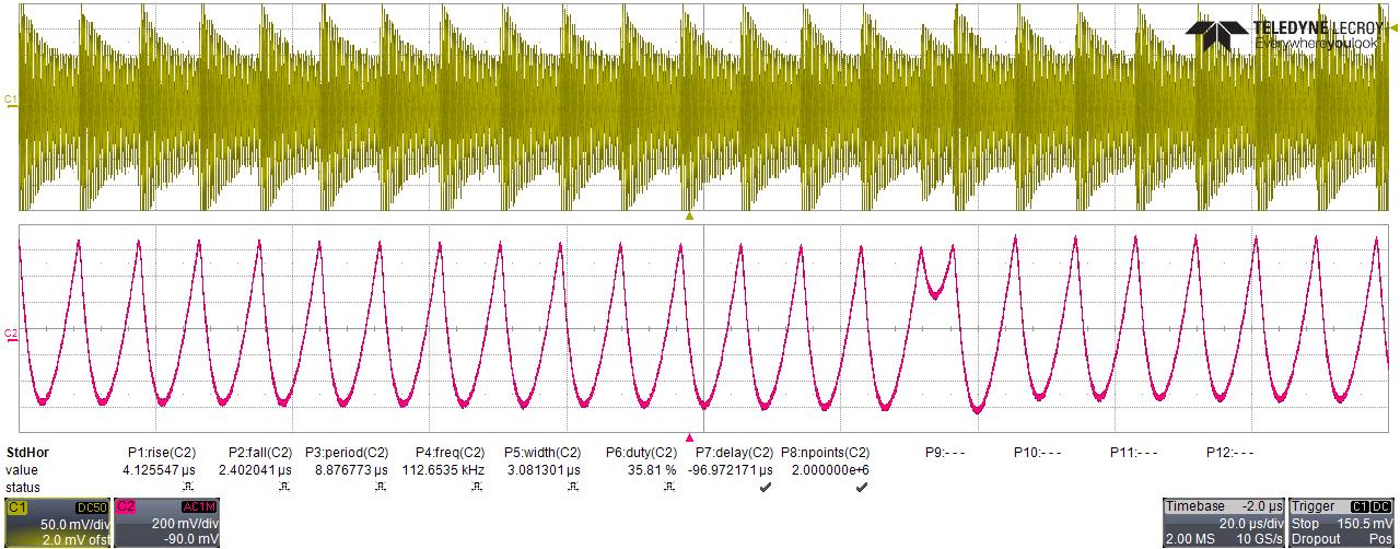
As you can see the measured voltage on CFB-pin is not steady. The Rp-value is not steady either(+-30). I tried to vary the values of Rpmax and Rpmin but it didn't help. The peak-peak-voltage is higher than the desired 1V so I tried another value for the Filter Capacitor.

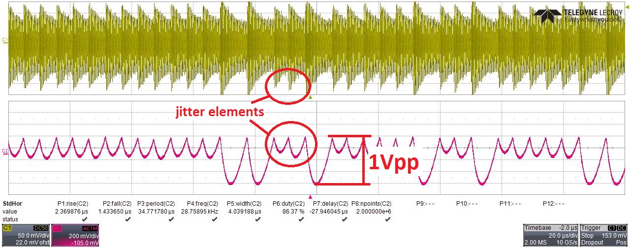
2. Filter Capacitor=33pF, air-coil

Now I’m closer to the desired 1Vpp at CFB-pin but this time it looks even worse. The Rp-value is very unstable (+-50).


3. No Filter Capacitor, air-coil

What I tried next is to remove the Filter Capacitor at all.

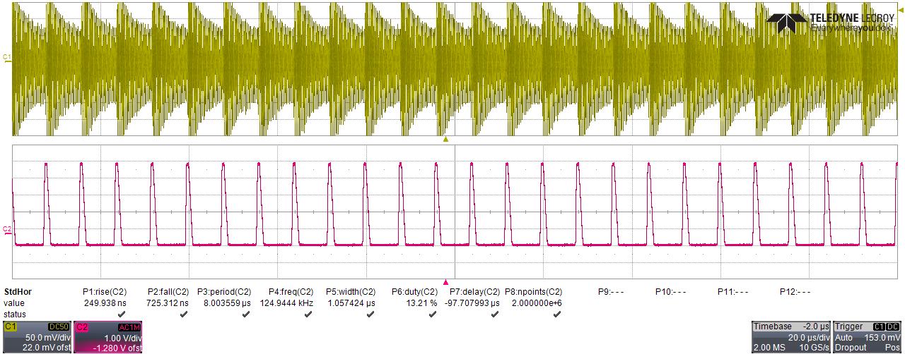
Now the voltage on the CFB-Pin is clipping(5Vpp). This time the Rp value is very stable(+-1).

It seems that removing the filter capacitor can lead to a smaller tolerance of Rp.
One problem: The small tolerance of +-1 is not true for all of my metal targets, but it’s not that bad.

In your datasheet you say that the voltage on CFB-pin should not exceed 1Vpp but my impression is that it gets better if the voltage is clipping at 5Vpp. Did I overlook any difficulties or is there a better way to stabilize Rp measurement? Could you please give me deeper info on the LDC internals so I can understand the purpose of the filter capacitor?

  • Hello Dieter,

    Thank you very much for such a detailed explanation. The voltage amplitude on Cfb should be 1Vpp for best noise performance. The filter capacitor sets the time constant of internal ADC. Therefore, removing it will introduce a large amount of noise to the measurement.

    What inductor/pcb coil are you using? For metal composition detection, the best operating frequency of the sensor is 200k-400k. You would also need a coil with a really high quality factor. If you could describe your target, that would also be helpful.

    Best Regards,
    Natallia Holubeva
  • Hello Natallia

    Thanks for your fast reply.

    Natallia Holubeva1 said:
    The voltage amplitude on Cfb should be 1Vpp for best noise performance. The filter capacitor sets the time constant of internal ADC. Therefore, removing it will introduce a large amount of noise to the measurement.


    I can’t really imagine the function of the filter capacitor yet. Which time can I set with it? Do you have any idea why the voltage on the cfb-pin has these “jitter-elements” in it even if I set the voltage to 1Vpp? I think that these “jitter elements” are the reason why the measurement is unstable.


    Natallia Holubeva1 said:
    What inductor/pcb coil are you using?


    I am using a selfwound air-coil (35uH) with high Q, but you can make the same observation with the standard unmodified EVM-board: When measuring without a target the Rp-value is not stable. If you remove the filter capacitor suddenly the Rp-value is stable (I used Rpmax=38,785k and Rpmin=3,078k). Do you make the same observation?

    Natallia Holubeva1 said:
    If you could describe your target, that would also be helpful.


    For the above oscillograms I didn’t use any targets

    Natallia Holubeva1 said:
    For metal composition detection, the best operating frequency of the sensor is 200k-400k

    .
    I'm going to try out a lower frequency in the next few days but the detection works at high frequencies too.


    Best Regards,
    Dieter

  • Hello Dieter,

    Q. : Why the voltage on Cfb should be 1Vpp?
    A.: The actual voltage on Cfb will change depending on target location. Without the target present, we advise to tune it to 1Vpp to make sure that the signal on the input of the ADC never hits GND or Rail voltages. If the ADC input hits either GND or Rail, it will mulfunction.

    Q.: Why the Cfb should be present in the circuit?
    A.: By having the right feedback capacitor, we reduce the damping of the oscillator, and allowing the ADC to respond faster to changes in the sensor.

    Please, try the following:
    1) Use this value for the Cf capacitor: Cf=22pF*3000/Ftank, where Ftank is in KHz
    2) Add a 33pF capacitor between pin INA and GND. Add another 33pF between INB and GND.

    Best Regards,
    Natallia Holubeva
  • Hello


    Natallia Holubeva1 said:
    Q. : Why the voltage on Cfb should be 1Vpp?
    A.: The actual voltage on Cfb will change depending on target location. Without the target present, we advise to tune it to 1Vpp to make sure that the signal on the input of the ADC never hits GND or Rail voltages. If the ADC input hits either GND or Rail, it will mulfunction.

    Q.: Why the Cfb should be present in the circuit?
    A.: By having the right feedback capacitor, we reduce the damping of the oscillator, and allowing the ADC to respond faster to changes in the sensor.

    So the ADC is a slope converter and the capacitor is the feedback-C for the integrator, right?


    Natallia Holubeva1 said:
    Please, try the following:
    1) Use this value for the Cf capacitor: Cf=22pF*3000/Ftank, where Ftank is in KHz
    2) Add a 33pF capacitor between pin INA and GND. Add another 33pF between INB and GND.

    I tried this, but the jitter is still there. I also tried it at 500kHz with higher capacitor values ... still jittering.

    Is there a way to get rid of this jitter or do I have to live with it?


    Best Regards,
    Dieter

  • Dieter,

    The shape of the waveform on Cfb pin is not as important as the amplitude. Also, please check your Rp values.

    Best Regards,
    Natallia Holubeva