This thread has been locked.

If you have a related question, please click the "Ask a related question" button in the top right corner. The newly created question will be automatically linked to this question.

LDC1612 EVM Coil Signal Drift due to Temperature

Other Parts Discussed in Thread: LDC1612, LDC1612EVM, LDC1101

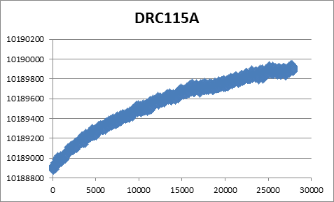
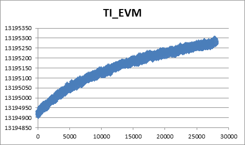
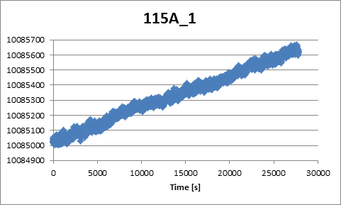
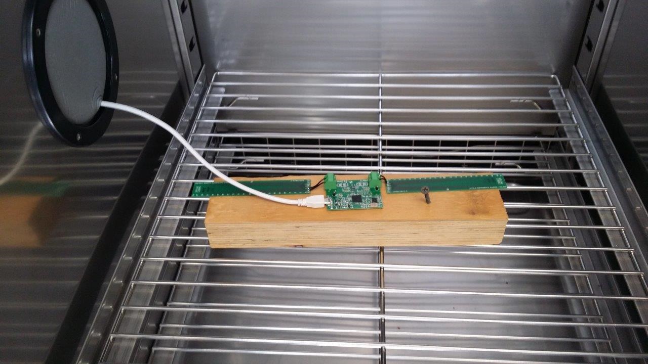
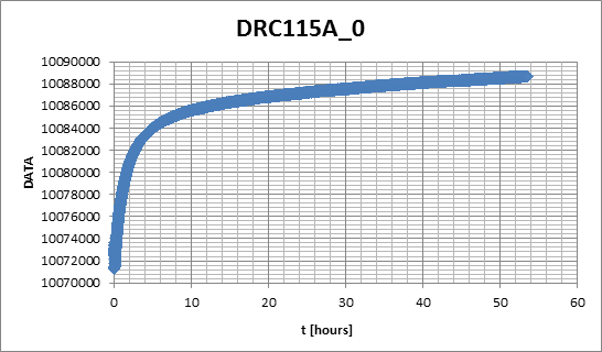
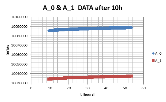
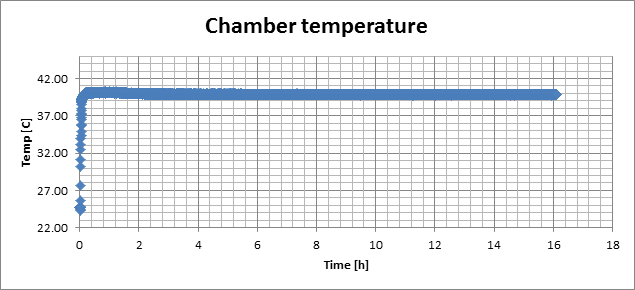
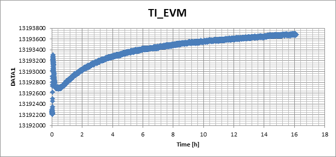
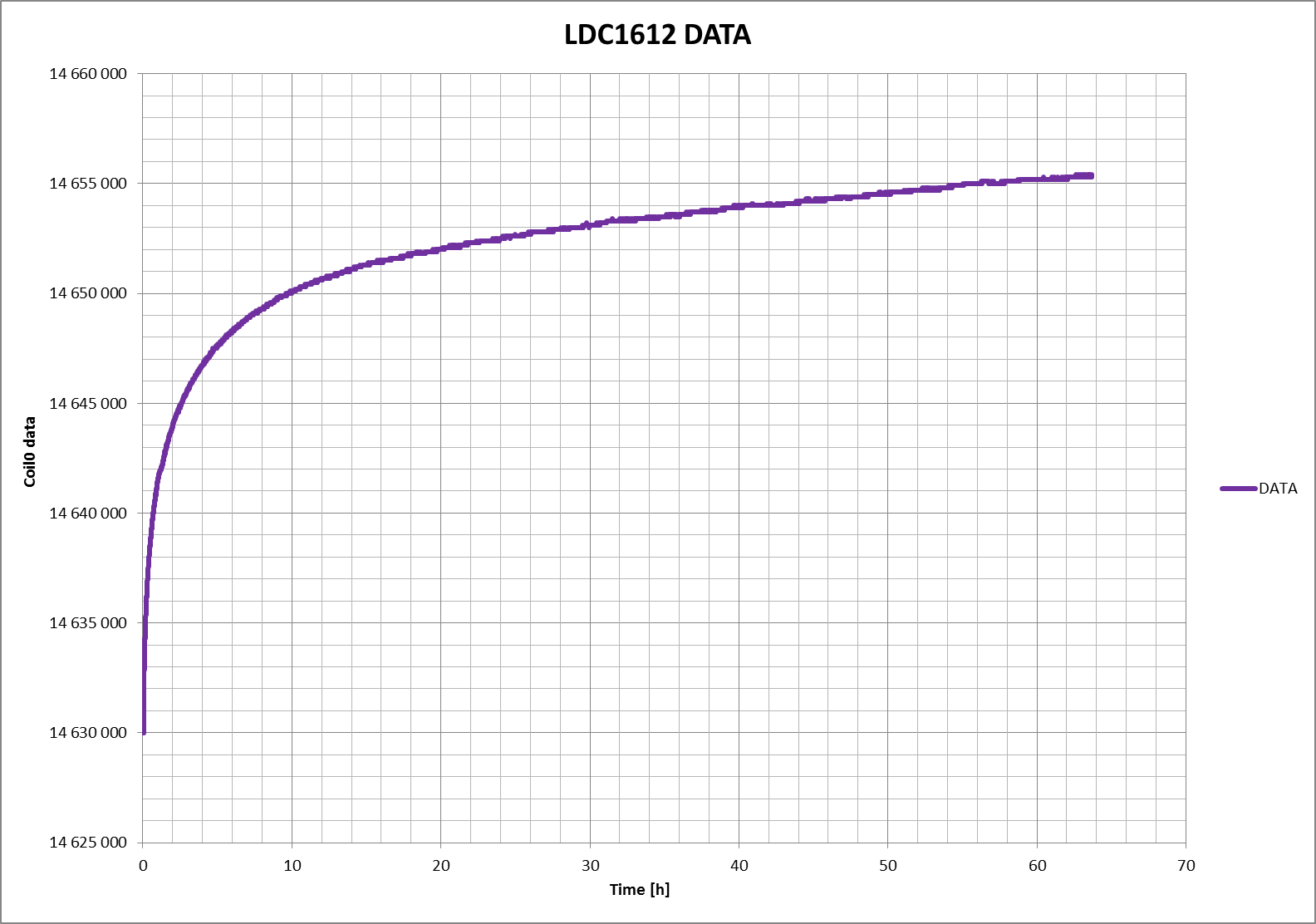
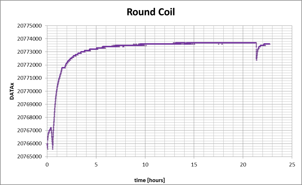
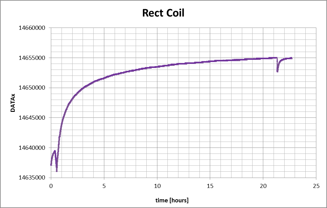
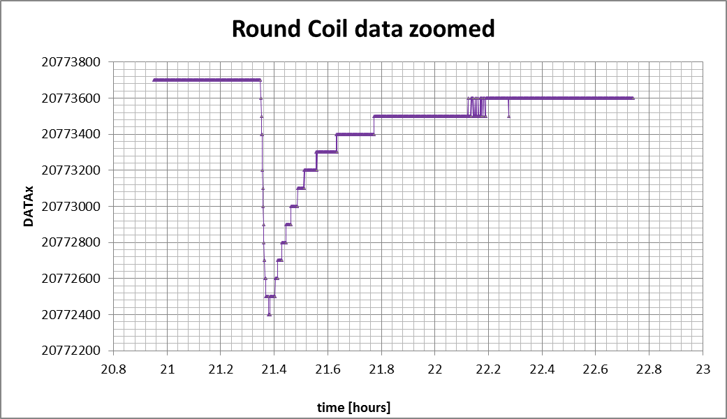
We have noticed that our rectangular 2-sided coils show a considerable drift that might be due to temperature. The drift can be order of thousands of units in couple of hours. In order to investigate this further we put the LDC1612EVM board with two coils into a oven. The temperature was 30C and we used our own coil as well as the circular coil that came with EVM. We assumed that the signal should be effectively a horizontal line with gaussian noise at least in the TI's coil, instead we got similar drift in both coils (see below). This is bit worrying as we use LDC1612 in linear position sensing and if the DC offsets in static temperature the product is unusable. The measurements below were made in period of 16 hours. 

We also noticed that there is a transient during the first couple of minutes when the coil adjusts to the external temperature. After that the actual drift starts. Are we doing something very wrong with the measurement parameters. The electronics used in this test was the LDC1612 EVM.


  • Hello,

    For the TI_EVm the code change is ~400, the signal is 13,195,100. This corresponds to 0.00003, or 0.003% or 30ppm change.
    How important is this miniscule change for your application?

    For your reference, C0G caps are specified at 30ppm change per degree C, so a small temp change may indeed have caused this drift.
  • The problem is that with AVX NP0 capacitor (100 pF 1%) the drift in our own coil in 8 hours is about 65ppm (see below). This happens in static temperature in oven. We see somewhat similar behavior with the TI's own coil. The question is that if there is a constant drift with 800 units/8 hours and our system is up and running for 90 days are the results anymore usable in linear position sensing. 

  • Could there be some other factors? How was the coil supported?
  • We did another measurement during the weekend. The initial temperature in the oven was 24 C and it was increased to 40 C. Below is a picture of the setup and the measurement results. After 10 h the oven is definitely in static temperature but the signal still shows a considerable drift. We are now doing the same test with the LDC1612 sample coil that came with the EVM. Could LDC measurement parameters affect the drift?

  • We remade the oven experiments, this time with our own coil and with TI's sample coil. We also put a precision thermometer into the oven. As can be seen from the figures the oven holds the static temperature pretty well. There might be a slight drift of about 0.1C but when compared to how the LDC1612 behaves this isn't enough to explain the drift. The LDC1612 coil and/or circuit drifts about 50 ppm for this 0.1C drift! I really, really would like to know what goes on in here. 

  • Hello,

    Is it possible to repeat this experiment with glass support instead of wood? I'd be very interested to see the results.
  • Hi Evgeny, Sami

    I've repeated a test similar to the one shown in Sami's post using a keralite substrate.

    I am using a rectangular coil rigidly attached to the substrate, and to our own PCB design utilizing LDC1612.

    The system is placed in a temperature chamber driving constant 30 degC starting from a ~25 degC at Time 0 hours.

    Chamber temperature settles typically in some tens of minutes, max some hours.

    Here is how the data looks like:

    I am interested of this drift phenomenon, because we are targeting to a system with DR between 10 000 to 100 000 data units of the LDC161x.

    What I would like to know is, that

    • Could this drift happen due some potential bad settings of the LDC1612 in our SW?
      • Are there some specific settings, which we should carefully review?
    • Do you recommend using the LDC1612 in always on configuration, or should it do periodic wake-up from sleep/shutdown to gain more accuracy?
      • Could the drift continue forever (or until the output saturates) in the always on use-case?
    • Do you have other concerns regarding the test setup, which could cause the drift? Environment temperature is constant.

      Thank You for your support!

  • Hi All,
    isn't it due to just some kind of material ageing? Coil copper oxidizing or something? Perhaps this drift has nothing to do with LDC1612 at all.

    Best wishes,
    Igor Gorbounov
  • Hello user4341326, Igor,

    While there is no mechanism in LDC1612 to drift with time (and only time!), it's important to understand on the system level, what is changing in the system to cause the drift.
    I would also monitor the xtal reference frequency and oscillation amplitude as a function of time. Drying of the PCB (and consecutive change of geometries) is also a major suspect, but it's difficult to measure accurately.
  • Hello,

    We were thinking about this drift, and came up with a couple of experiments. Is it possible for you to run them and post the results?
    1) Run the experiment for a few hours, then open the door of the chamber, leave it open for a few seconds, then close again. Post results of full run, and zoomed-in version on door-open event, and door-close event. Or just post an xls with time stamps
    2) Run the experiment with the door open, but blocked with a piece of plastic/wood
  • Hi Evgeny, all
    Thank you for the suggestions & advice!


    Effectively, we don’t know yet what in our prototype system causes this drift. Today we can’t completely disregard the clocking path, or other system level errors yet. The sensor – PCB coil + NP0/C0G Cap – however, is considered “clearly” as the most inaccurate part of the system, and the assumption is that we are essentially measuring the behavior of the sensor. As the time constants, which we are observing in the temperature behavior of the system, are so long (data doesn’t settle in 50-60 hours in stable environment) I became slightly worried about that are we really measuring the sensor thermal behavior.


    Anyway, here is a test where I think I am doing something similar what was suggested.
    HW is custom build based on reference design, SW is also developed for this board – reporting basically only the LDC data to the host. There is one HW setup in the chamber with TI LDC1612EVM round PCB coil and another with rectangular PCB sensor intended for linear position sensing.
    •    In the beginning  the system is started chamber door open
    •    After roughly half an hour, the chamber door is closed and chamber operation is started to drive constant 30C
    •    After roughly 21hours of untouched logging, the chamber door is opened for few seconds and closed again.

    Here are the graphs, Ts = 5s, time in hours is presented as plain decimal number e.g 45 min = 0.75 hours.

    In the point 2, are you suggesting to run the whole test with the chamber door open, while the chamber is operating?

  • I am currently evaluating the LDC1612 with a custom coil design, and I also have observed thermal drifts. My coil is a circular 4-layer design with 18 turns, an outer diameter of 17 mm and an inner diameter of 5.5 mm. I placed two 4.7 nF capacitors (C0G) on the coil PCB to have 9.4 nF in total. This results in a sensor frequency of roughly 300 kHz.
    The coil is placed remote from the LDC1612 on a different PCB. The two PCBs are connected via two solid copper wires (0.5 mm diameter, 20 mm length), so if I take my whole sensor and move it around, the measured inductance does not change; the connection is stiff enough, I suppose. For my experiments I placed the whole sensor system on a plastic block and put it in an oven. As soon as I powered the LDC, I observed a drift in the sensor output code. Since the change seemed to settle after a while (about 20 minutes), I assume this was due to self-heating of the LDC1612 and the coil. This change was rather small (about 1000 digits in total).
    After the "self-heating" had settled, I powered the oven and set it to a temperature of 60 °C. The LDC output code changed with temperature, but settled about 2 hours after reaching the target temperature. Altogether I had a drift of about 200 ppm/K.
    I have tracked down the source of the thermal drift down to the sensor coil. The LDC might have a small variation in temperature, the C0G capacitor should have less than 30 ppm/K, the reference clock source is even better according to the manufacturer. So the PCB design has to play a major role.
    I have considered [1], as it mentions that there could be a special coil design which can be temperature compensated (see section 2.2). It also cites [2], which gives mathematical models for the calculation of multilayer spiral inductors. I assume these models are somewhere working in the Background of the WEBENCH tool, too. I have implemented these models in GNU Octave to verify my design and to simulate the effects of thermal Expansion on the total inductance of my coil. According to my simulation, the total inductance variation should be about 20 ppm/K (I was observing ten times as much). Also, there is no chance of having a temperature compensated 4-layer design, since the change in inter-layer coupling is considerably larger than the change of single-layer inductance. I could (theoretically) get a total variation of less than 5 ppm/K, but only using a 2-layer design with a 1.8 mm PCB.
    Interestingly, when I compare the results of [2] to the results of the WEBENCH tool (using the same coil design), there are huge differences. The WEBENCH design results in a total inductance of 53 µH, which matches the practical experiment. Using the calculations from [2], I get a total inductance of more than 70 µH. Some of the derived design parameters (fill ratio, inner diameter) also differ, and especially the fill ratio (which is an important design Parameter) seems to be calculated differently.
    [2] also refers to [3], from which the calculation of a single-layer coil is taken. Although the accuracy of the calculations in both reports is very good, [3] states that they used inductors for RF applications, with diameters from 100 µm to 480 µm and a total inductance of 0.5 nH to 100 nH. This is considerably smaller than all LDC sensor designs I have encountered, which makes me wonder if the calculations are applicable to LDC sensor coils with good reliability.

    Do you know of any reference designs which have a temperature compensated design? Has anyone of you tried to verify the coil design by numerical simulation?

    References:
    [1] "LDC1000 Temperature Compensation", TI Application Report, SNAA212
    [2] "A new calculation for designing multilayer spiral inductors", EDN37 (2010/07/29)
    [3] "Simple Accurate Expressions for Planar Spiral Inductances", IEEE Journal of Solid-State Circuits, Vol. 34 (1999/10/10)
  • Was this problem with drift ever really solved? I guess your data shows that the drift cannot be caused by a changing temperature so I wonder what else could have caused it.

    I am currently working with the LDC1101 with a custom coil and I'm experiencing the same problems with drift. I've placed an aluminum target at 1 mm distance of the coil and measured an increase of 500 points / hour. Since I'm also looking for a long term application (one week) this is unacceptable. In one of the previous comments it was suggested to shut down the sensor in between measurements. I've tried this (1 minute on, 1 minute off) but in a session of 12 hours I got exactly the same results as without shutting down. Are there any other suggestions to solve temporal drift?

    Kind regards,

    Bob
  • Hello,
    I know it's too late for the OP, but I faced a similar behaviour and I want to share my experience.
    I solved the issue replacing the random capacitor found in the lab with a Philips NP0, now my diagrams are stable.
    I hope my post can help someone else.
  • NP0/COG capacitors are a must-have for any analog application which is sensitive to temperature. Considering the LDC resolution, you can observe even the smallest change in any temperature-dependent part of your whole system. By now, I have done a lot of experiments regarding temperature, and I think there are some major points you should always consider when designing a high precision LDC application:

    • Trace the whole signal path from the coil to the LDC. Look for every single (discrete or parasitic) capacitance that could change with temperature. Try to minimize it as far as possible in the design stage.
    • When you already have a PCB, use a soldering iron with a small tip set to 100 °C and selectively heat some critical spots on your PCB/in your circuit. Watch the LDC Output. You will easily discover which parts and which components are sensitive to temperature.
    • Use NP0/COG capacitors at least for the tank capacitor (as already noted in some TI application notes for the LDC).
    • Try and develop some sort of compensation technique, if necessary. We did, and it works even for long-term measurements, but unfortunately I am not allowed to tell any details.

  • Thanks Giacomo and Torben,
    I agree, switching to a NP0/C0G is highly recommended to minimize drift over temperature. These capacitors are rated to +/-30ppm/ degree C.
    This apps note has more information on temperature effect and compensation techniques: www.ti.com/.../snaa212.pdf
    This reference design shows how a multi-channel device can be used to compensate for temperature effects to a very high degree: www.ti.com/.../TIDA-00508