This thread has been locked.

If you have a related question, please click the "Ask a related question" button in the top right corner. The newly created question will be automatically linked to this question.

LDC1000: 4 layer PCB COIL LAYOUT

Other Parts Discussed in Thread: LDC1101

Hello, 

I'am using LDC1000 device with CTANK = 1nF and Lpcbcoil= 82uH (below the 4 layer PCB COIL LAYOUT used). 

All vias are blind and buried, except that left via. The central via have a diameter of 0.6/0.8mm, while the others have a diameter of 0.2/0.3mm  . The copper tickness of coil is 42um for external layer and 35um for mid-layer, and the coil external diameter is 15.6mm .

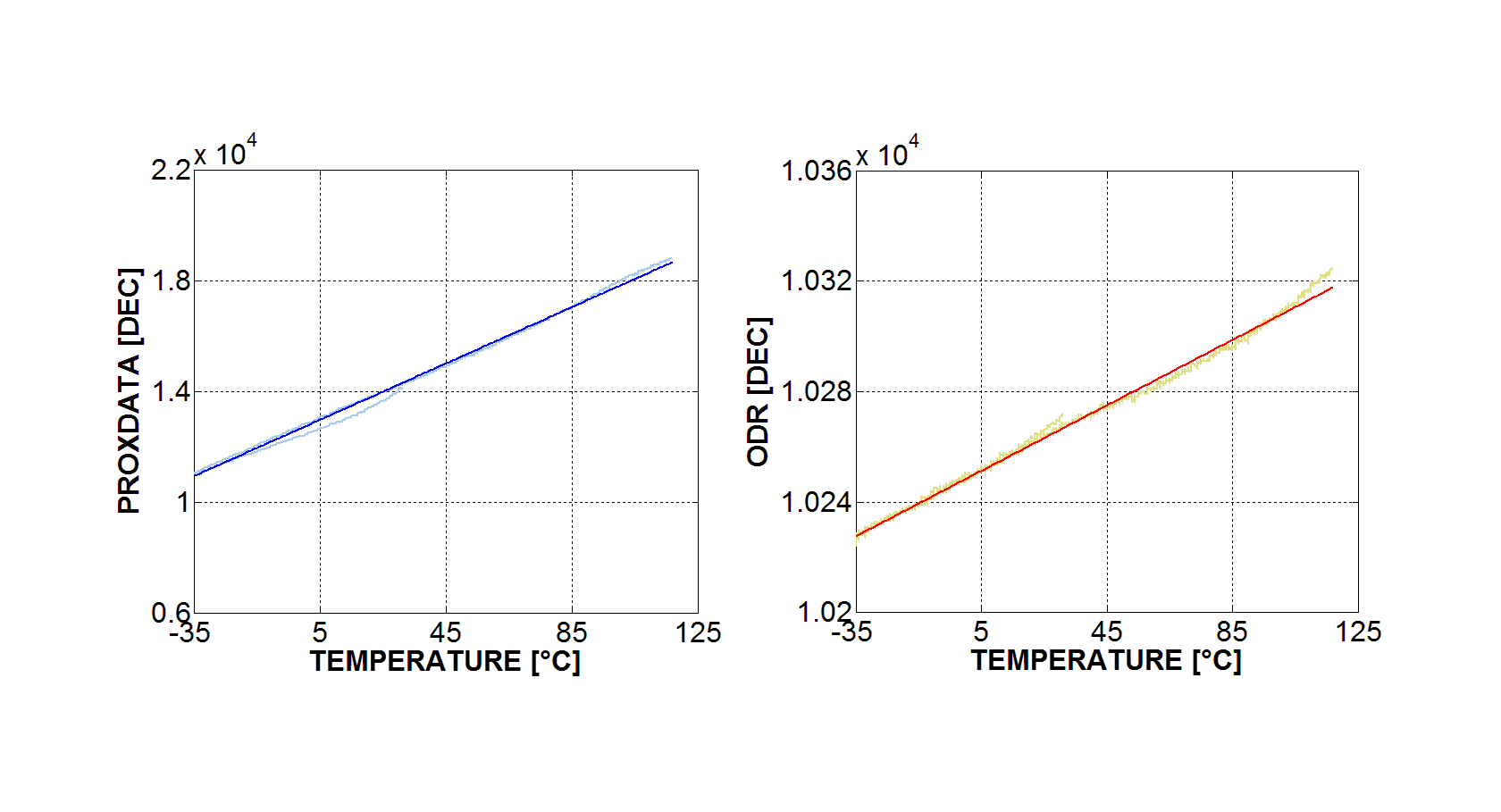
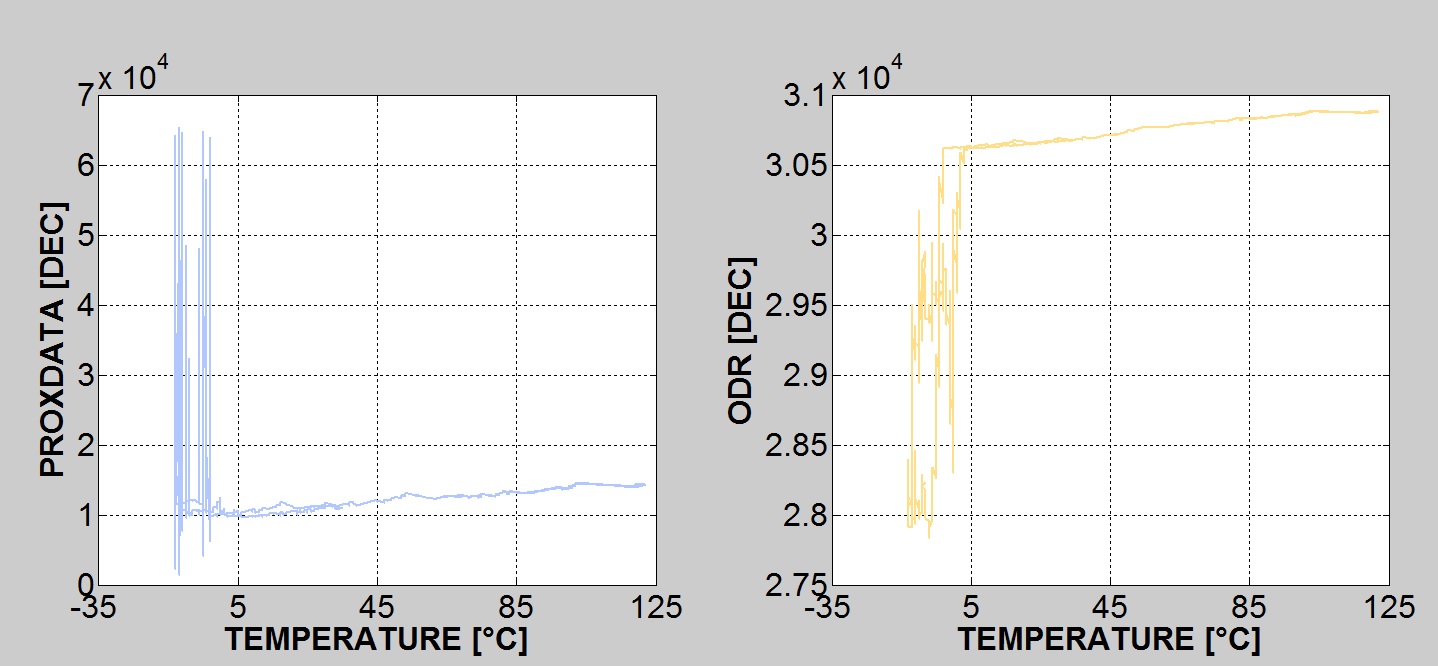
I performed a temperature test with this pcb coil, and I seen that for TEMP < 5°C, the ODR and PROXIMITY DATA behavorial is very strange (see below).

I take also care that the Rp escursion keep within the range [ 0.798 , 3926.991] kΩ .  

Why does the COIL behave in this way ?? I think the problem is due to the geometry of COIL, but it's really so ?? 


  • I would check what's going on at CFB pin at low temperature. I suspect clipping

  • I used a CFILTER capacitor (between CFB and CFA pins) NP0 of 100pF in such way the peak-peak voltage on CFB pin is 1V .

    I tried with other board using a CFILTER capacitor NP0 of 20pF, but the result is same.

    I also tried to use other pcbcoil (L = 15uH) with CTANK = 100pF on the same board, and the problem doesn't show .

    How can I risolve the problem ??


    With best regards,

    Carmine Mennillo
  • Hello Carmine,

    It is possible that you have a PCB manufacturing issue with the coil. For example, if one of the vias is not well formed, this could produce continuity issues.

    Regards,

    ChrisO 

  • Hello,


    What is the Fref value in your system?

  • My system Fref is 500kHz.


    With best regards,

    Carmine Mennillo
  • Hi Chris,

    I tried to meas the pcbcoil series-resistance for many different temperature with multimeter, verifying that no continuity issues exist (the Rs increase linearly in temperature).

    Furthermore, I tried to reduce the CTANK capacitor by 1nF to 100pF (using the 4 layer coil shown above), and the strange behavior seen previously doesn't show. Why does happen this ?? Does it exist a reason for which this happen ?


    With best regards,

    Carmine Mennillo
  • Hello,

    I'm using the 4 coil layout shown above for linear position application.

    We are still having problem with the temperature test: the graphic show below are obtained  keeping target in a fixed position. The temperature is set by -30°C to 100°C starting from room temperature and with a gradient of 0.5°C / minute .

    If we not the ODR curve we can see an hysteresis due to transient temperature of target (sensor and target have different temperature because the sensor reach first the set current temperature).

    If we remove the target, the ODR curve is perfectly linear as below.

     Have you ever experienced this situation ?   

  • Hello,

    To clarify: the Fref (frequency applied to the TBLK pin) is 500kHz? I would expect your sensor frequency to be ~500kHz. A higher reference frequency provides better measurement resolution.

    As for the hysteresis-type response to the target, is it possible that you have some mechanical fixture instabilities? It can be tricky to ensure that the target is not really moving due to thermal expansion of many mechanical systems. We often use precision glass spacers (which have a very low thermal coefficient of expansion)for temperature measurements with targets to avoid such effects.

    Regards,
    ChrisO
  • Hello Chris,

    Fref of my system is 8MHz (there's a quarz on Xin Xout). 500kHZ is the resonance frequency of the oscillator circuit LC.

    is there any LDC that can works over the 8MHz frequencies?

    Regarding the mechanical instabilities we use a metallic structure to keep the sensor + target hold in a fixed position.

    We develop te sensor for our customer who install it on its gear box, so we can't predict the signal variation due to temperature mechanical dilatation because we haven't the mechanical part of our customer (i believe that is not yet fully developed from customer side). LDC1000 is very hard to use in automotive application where the operating temperature ranges are very extreme ( from -40°C to +125°C in our application). To characterize the sensor we should have the mechanical part of our customer and than we should repeat the test in a climatic chamber with the entire system (maybe the system can not enter in the chamber).. Even if we could characterize the sensor, it would be used only coupled with that mechanicl part.

    Best regards

  • Hello Carmine,

    It is possible the mechanical system you use to position the target is causing the hysteresis-type response when temperature cycling.

    As for your question on LDC products which operate with Fref>8MHz, the multi-channel LDC161x and LDC131x devices can support up to 40MHz for the reference frequency, and the LDC1101 can operate with a 16MHz reference frequency.

    Regards,

    ChrisO