This thread has been locked.

If you have a related question, please click the "Ask a related question" button in the top right corner. The newly created question will be automatically linked to this question.

TDC1000-BSTEVM output

Other Parts Discussed in Thread: TDC1000

Hello

With reference to my previous post located at this link https://e2e.ti.com/support/sensor/ultrasonic/f/991/t/422763

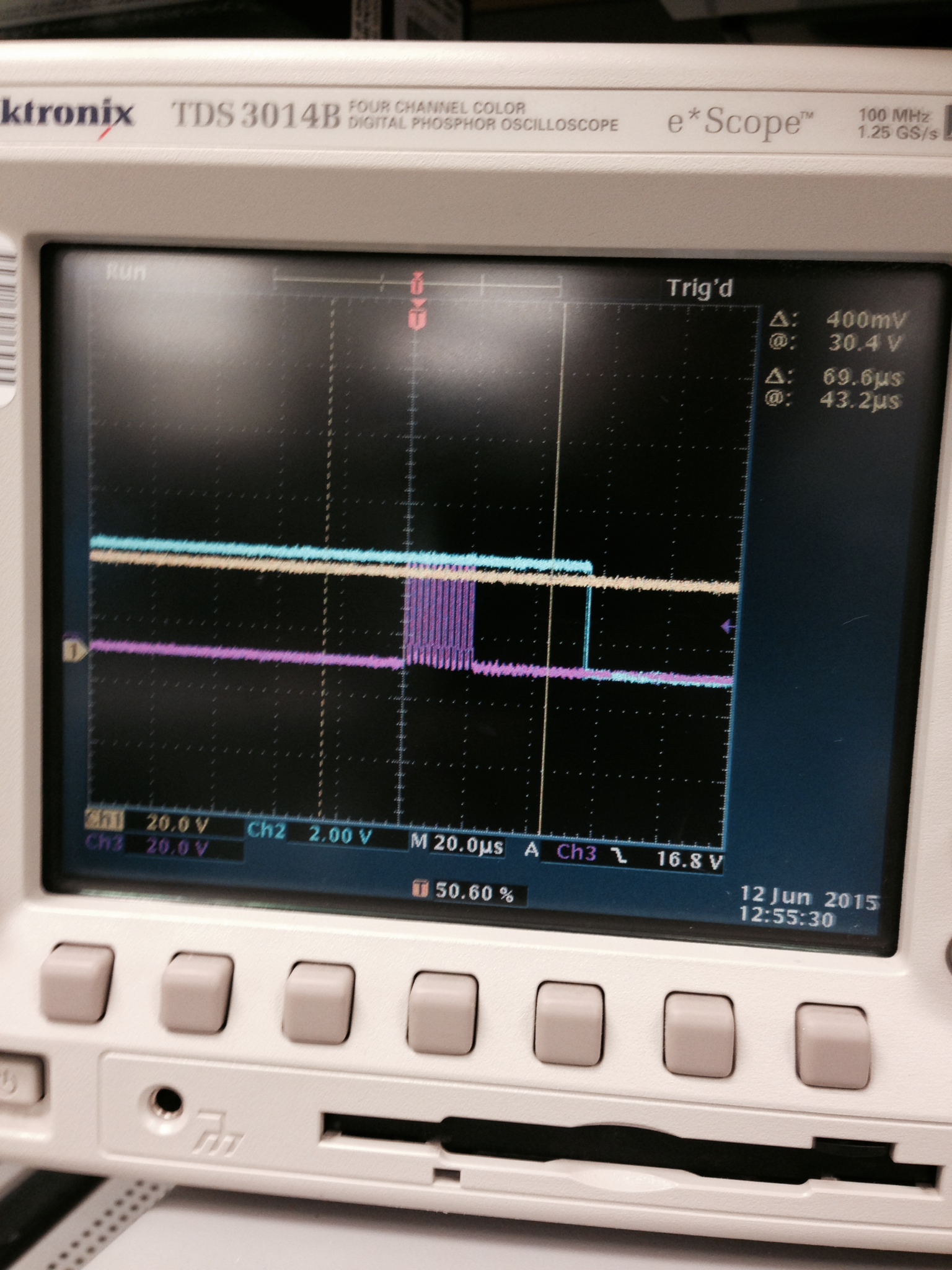
We ordered a new board and followed the same procedure to get the 30V output on the TP2(30V) pin. But it looks like the new board is also not giving the desired results. 

Could you please guide me how to debug this issue?

  • To resolve this issue, please do the following

    a) Enable "TDC1000-HV Boost Power Enable" checkbox in setup page  

    b) Set the enable period as 150000. This field in GUI is actually us not ms. I think insufficient enable period is causing the issue.

    Thanks,

    Vishy

  • HI

    The "TDC1000-HV Boost Power Enable" checkbox in setup page was already enabled. On changing the enable period there is no change observed in the output  

  • I am checking this with the board designer. I will come back to you soon. thanks, Vishy
  • I got a TDC1000-BSTEVM setup with a TDC1000-GASEVM board and tested this issue. Enclosed here is the config file (TDC1000_Setup_gasevm.txt) I used. Once you are connected with the GUI to the TDC1000-GASEVM board, please load this config file. It sets up all the registers as well as the other parameters. Ensure in TDC1000 Register page "CONTINUOUS_TRIGGER" switch is ON (green). To check the board's functionality, I connected three scope probes on TDC1000-BSTEVM board: CH1 Yellow on TP2 (30V), CH2 Teal on J4.10, CH3 Purple on U2.6. Trigger is set on J4.10, falling edge. You can see the output in the enclosed scope shot file tdc1000-bstevm.jpg

    As you can see, the amplified transmit pulses are 30V level.

    Thanks,Vishy

    TDC1000_Config0                         2B
    TDC1000_Config1                         45
    TDC1000_Config2                         16
    TDC1000_Config3                         02
    TDC1000_Config4                         1F
    TDC1000_TOF-1                           A0
    TDC1000_TOF-0                           1E
    TDC1000_Error_Flags                     00
    TDC1000_Timeout                         63
    TDC1000_Clock_Rate                      07
    TDC1000_Conts_Trigger                   01
    TDC7200_Config1                         02
    TDC7200_Config2                         44
    TDC7200_Interrupt_Status                07
    TDC7200_Interrupt_Mask                  07
    TDC7200_Coarse_Cntr_Ov_H                FF
    TDC7200_Coarse_Cntr_Ov_L                FF
    TDC7200_Clock_Cntr_Ov_H                 FF
    TDC7200_Clock_Cntr_Ov_L                 FF
    TDC7200_Clock_Cntr_Stop_Mask_H          00
    TDC7200_Clock_Cntr_Stop_Mask_L          00
    TRIGGER_UPDATE_FREQ                     0003
    TDC_AVG/STDEV_NUM_ELEMS                 000A
    SAVE_GRAPH_DATA_TO_FILE                 00
    FLOW_MODE_SELECT                        01
    Y-SCALE_CENTER                          0032
    X-SCALE_RANGE                           0032
    MEASURE_RTD1                            00
    SAVE_RESULT_REGR_TO_FILE                00
    GRAPH_MULTI_STOPS                       00
    TDC_SELECT                              03
    TEMP_RTD_SELECT                         00
    TEMP_RTD_MODE                           01
    TEMP_AVG/STDEV_NUM_ELEMS                000A
    SAVE_TEMP_DATA                          00
    GRAPH_YMAX_DATA                         000000008CCCCCCC
    GRAPH_YMIN_DATA                         000000007FFFFFFF
    TDC1000-HV_DRV_EN1                      01
    TDC1000-HV_DRV_EN2                      01
    HV_DRV_EN1_Period                       02BC
    HV_DRV_EN2_Period                       012C
    ENABLE_POWER_CYCLE                      00
    CLK_FREQ_(1-16MHz)                      2.000000
    CLK_SOURCE_SEL                          02
    CPU_CLK_FREQ                            0C
    CPU_CLK_EN                              01
    TDC1000-HV_BST_PWR_EN                   01
    HV_BST_PWR_EN_Period                    3A98
    FWD2REV_FLOW_DELAY                      0000
    TDC1000-IMPE_MATCH_EN                   00

  • Hey Vishy.. Thanks for testing this for us. This new configuration worked out for us. Main problem was with original board's broken boost converter. We ordered new board and that one seems to be showing expected behavior.

  • Thanks for letting us know.