This thread has been locked.

If you have a related question, please click the "Ask a related question" button in the top right corner. The newly created question will be automatically linked to this question.

LDC1614 strange sensor oscillation waveform

Hi TI team,

I have a strange waveform splash in the beginning of each sensor measurement cycle:

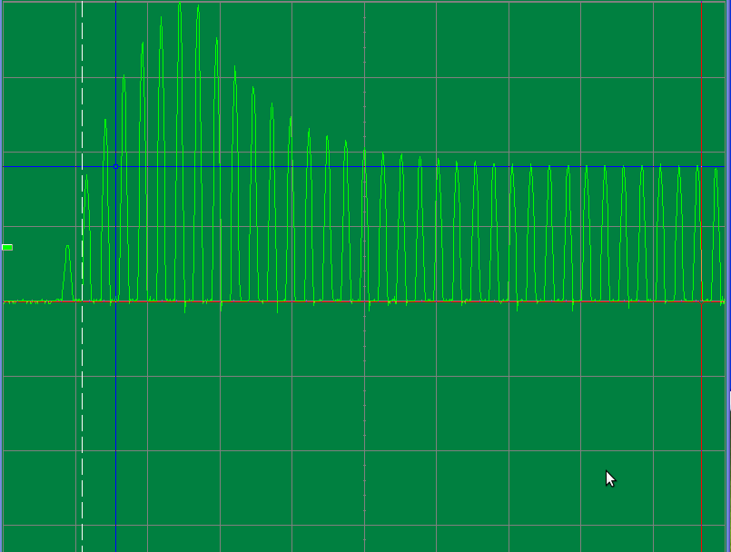
Scale here is 0.5V and 2 us per division. Our coils are 14 mm in diameter, 8.9 uH, 5.1 Om and condensators are 820 pF.

It can be seen that INA or INB signal splashes up to 2 V and then becomes steady at about 900 mV. Is this a proper behaviour?

Sensor current drives are 0xC000, amplitude autocorrection is disabled. Which else parameters are vital for stable

sensor work?

I'm concerned with ocasional sensor mesurement data variations, don't know the cause of it.

Best wishes,

     Igor Gorbounov

  • Hello Igor,

    The sensor stimuli you noticed is fine. Please make sure the RP_OVERRIDE_EN is disabled. Try setting SENSOR_ACTIVATE_SEL to 1 for a more controlled sensor initialization.

    Regards,

    Chris O
  • Hi Chris,

    Now this signal is smoothly rising up, just like in the data sheet!

    Thank you for advice!

    Now the signal amplitude seems to be about 0.9 V. Should it be raised to 1.2 - 1.8 V?

    Best wishes,

        Igor Gorbounov

  • Hello Igor,
    I apologize for conflicting information. For precision applications, RP_OVERRIDE_EN should be enabled (set to 1). Then, you can use the CHx_IDRIVE setting to find the optimal drive current. The drive current setting should be determined when the target is at its maximum position which it will be in in the final system. The optimal IDRIVE setting is the largest setting that produces an oscillation amplitude of <1.8Vpk.
    The waveform in your scope shot will work, but SNR can be further optimized by increasing IDRIVE (while staying below the 1.8Vpk limit).