This thread has been locked.

If you have a related question, please click the "Ask a related question" button in the top right corner. The newly created question will be automatically linked to this question.

FDC1004 - difference between four channels

Hello!

I've intialized  FDC to measure four channels. 

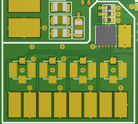
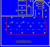
I make sure that shielding and grounding is done properly (according online docs and guides, fdc datasheet). Problem is, that  results are really strange:

result_f:   0.7384   0.6925   0.4066   0.4079

As you can notice, first two channels (from left to right) have almost double initial value than channels 3 and 4. There was no aditional capacitor added to circuit. 
I understant that this two capacitors are slightly further away, but in this case it should be somehow proportional (also channel 3 should have larger initial capacitance). 

When inserting aditional 1pF (the same capacitor for every channel) capacitor to any of those channels, capacitance increases wierdly:

result_f:   1.137   1.242   1.006   1.008

Now I'm really confused:

- what could cause such large initial capacitance difference  between channels?

- why adding another 1pF (the same capacitor) to every channel doesn't increase value for about 1.
approximately delta: 0.395  0.548  0.599  0.600
Shouldn't delta be about 1 (+/- 10%  for usual ceramic capacitor)?

- what happens if sheield capacitance is overloaded: larger than 400pF?

- could measurement method (REPEATED or SINGLE) anyhow affect the reading? 

Thank you for your support:

Domen. 

  • Hi domen:

    One thing that I can think of that is causing a difference in values would be its location relative to the GnD source. If you use our EVM without the sensors attached, you will see that the capacitance values are fairly similar, not exactly the same due to initially trimming of the device.

    Would you please supply a PDF of the layouts so I can have a better look at it?

    Also how is your measurements configured?

    Thanks

    David Wang

    Capacitive Sensing Applications

  • Hello, thanks for quick reply. 

    "One thing that I can think of that is causing a difference in values would be its location relative to the GnD source."
    Yes, each pin is shielded, but also has some ground beneath it. Here are 8 pads (signal and shields), and above them 4 IPX connectors, which are not soldered. Under IPX connectors there is shield. Under 8 pads, there is GND, but it is the same "shape" for all capcitors, so it should not affect on the difference, just initial offset which would be the same, as far as I understand. See the attached PDF. 

    "If you use our EVM without the sensors attached, you will see that the capacitance values are fairly similar, not exactly the same due to initially trimming of the device."
    Just out of curiosity: I don't have your EVM, but: shouldn't factory trimming completely eliminate device initial reading? Meaning, without any external circuitry, FDC should read zero or something like this?

    Anyway, initial offset isn't what concerns me, it can be easily eliminated in software. But the change (delta C) when adding additional 1pF capacitance is just not as it should be. It make me think that capcitance reading is not "linear" - like channels have different gain, which is really strange. 

    My settings of FDC:

    Each capacitor on its own channel, CAPDAC disabled. 
    RATE: 100S/s
    OFFSET_CALn: 0
    GAIN_CALn: unchanged

    These measurement were made with software averaging (3 or 8, the result is simmilar).

    Thanks, domen

  • Hi Domen:

    This application is for captouch buttons correct? One thing to mention is your sensitivity of your buttons will be significantly reduced due to the GND pad underneath it. The weird thing is that your initial capacitance values are small. Those values are what you would expect if you did not have a GND pad underneath your sensors, with them, I would expect a few pF's. Could you attach the PDF, there was nothing attached.

    In terms of factory trimming, yes, with the device itself, it should be around the same values, but once you connect traces to the pins, the capacitance from the traces will start affect the measurements even though you may not have any other components on the signal line.

    There is some slight gain error as mentioned in the specs in the datasheet and each channel will be slightly different, should not be noticeable unless you are using a highly precise measurement tester, but what you are seeing should not be that bad. How exactly are you connecting the additional 1pF cap on to your circuit?

    Thanks

    David Wang

    Capacitive Sensing Applications

  • "This application is for captouch buttons correct? One thing to mention is your sensitivity of your buttons will be significantly reduced due to the GND pad underneath it.The weird thing is that your initial capacitance values are small. Those values are what you would expect if you did not have a GND pad underneath your sensors, with them, I would expect a few pF's."

    It is not captouch button, it is custom capacitive force sensor.  Additional capacitance due gnd pads beneath signal pads is around 0.2pF (formula: C=eps*eps_r*A/d). Why would sensitivity be reduced? Shouldn't this additional capacitance just lower sensing range, while it can be eliminated with CAPDAC if it is larger than 3.125pF?


    "Could you attach the PDF, there was nothing attached."

    Sorry, it is attached now. 


    "In terms of factory trimming, yes, with the device itself, it should be around the same values, but once you connect traces to the pins, the capacitance from the traces will start affect the measurements even though you may not have any other components on the signal line."

    Yes, so it is as I thought. The problem is because this initial capacitance is almost twice larger on first two channels as the third and fourth. There is not much difference in distance or layout, so this is strange, but not an obstacle. Delta is much bigger problem. 

    "There is some slight gain error as mentioned in the specs in the datasheet and each channel will be slightly different, should not be noticeable unless you are using a highly precise measurement tester, but what you are seeing should not be that bad. How exactly are you connecting the additional 1pF cap on to your circuit?"

    Ok, that makes sense, although the difference is really too big. I would like to measure 4 channels - 4 identical sensors, and for the same force reading should be the same. Additional 1pF is simply soldered to any channel between signal pad and gnd pad.  

    Just a though? Could FDC be damaged if large capacitance, or short circuit is applied between signal pad and shield pad? 
    Could shield driver be "amplified" so capacitance could be larger than 400pf?

    Thanks, you are very kind for helping me out.  I will try another board with FDC and see where is a problem. 


    printout.pdf

  • Having a GND pad underneath your primary sensor will decrease your sensitivity/sensing range because most of the electric fields will be in a parallel plate fashion. If you are doing proximity sensing from the top side, most of the electric fields will still be dominate underneath the plate, hence decreases your sensitivity. You cannot eliminate this with the CAPDAC because it is seen as a gain error rather than an offset.

    your initial capacitive seems feasible. Your trace lengths for two of the channels are almost twice as long as the other two, and with the ground plane underneath, I would expect to see that much parasitics to be seen in your measurement. If you want them to have the same cap, try to use the GAIn and offset registers or to match the trace lengths.

    For using the 1pF cap, where are you soldering it? From the looks of the layout you would need some wires to connect it between CINx and GND. If that's the case, then that is why you are not seeing the 1pF cap, because of the layout and the difference when connecting it to each of the 4 channels.

    FDC should not be damaged if a large capacitance is applied. A short between signal and SHLD may cause a problem. There is no why for the SHLD driver to amplify more than 400pF. You can determine if your SHLD is being saturated is by probing the line and making sure there is no rounding off of the square wave signal.
  • David Wang11 said:
    Having a GND pad underneath your primary sensor will decrease your sensitivity/sensing range because most of the electric fields will be in a parallel plate fashion. If you are doing proximity sensing from the top side, most of the electric fields will still be dominate underneath the plate, hence decreases your sensitivity. You cannot eliminate this with the CAPDAC because it is seen as a gain error rather than an offset.

    Let me explain another "problem". We've got capcitive force sensor, that is capable of "measuring" push and pull force - so capacitance is larger and smaller corresponding to applied force. In order to measure both (pull and push), I've added external capacitor to sensor in order to increase capacitance and than lower it to wanted middle point of range with CAPDAC (15pF range was splitted to 7.5pF for push force and 7.5pF for pull force - inital capacitance reading is around 7.5pF +/-CAPDAC reslution/2. If I understand you, this added capacitor is lowering my sensitivity due "most of the electric fields will still be dominate underneath the plate"  ? Is there any other way to achieve such acting (measuring +/- capacitance) with FDC? 
    p.s. I don't need to know the capacitance in pF. I just need to know raw number from sensor, it is later used to calculate force...

    David Wang11 said:
    For using the 1pF cap, where are you soldering it? From the looks of the layout you would need some wires to connect it between CINx and GND. If that's the case, then that is why you are not seeing the 1pF cap, because of the layout and the difference when connecting it to each of the 4 channels.

    That was exactly it. I changed GND wire with larger diameter, and solder all caps GND to same point, and the problem disapeared. Thank you. 


    Thank you for your help so far. 

  • Have you measured your sensitivity of your system with the external capacitor added? Sorry but I had the wrong statement implied. Adding an external capacitor in parallel to your sensor should be fine and give you that offset, but doing it that way you are subjected to variations in capacitor value due to tolerance. The "most of the electric field will still be dominate underneath the plate" statement was specifically for the GND electrode underneath the sensor electrode.

    Thanks
    -David Wang
    Capacitive Sensing Applications