This thread has been locked.

If you have a related question, please click the "Ask a related question" button in the top right corner. The newly created question will be automatically linked to this question.

LDC1000-GASEVM ignores the first echo and sensing 2nd echo.

Other Parts Discussed in Thread: TDC1000, UCC27531

I bought LDC1000-GASEVM and try to measre the water depth in my tank.  

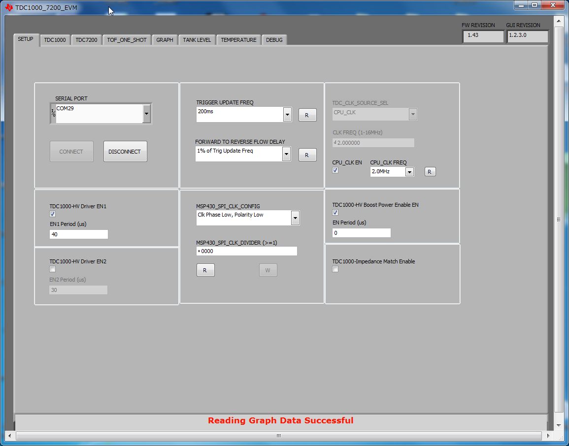
I use TDC1000-TDC7200EVM GUI v1.2.3.0 (Rev. E)  to control it. 

I filled the tank with water up to about 6 cm to see the signal. 

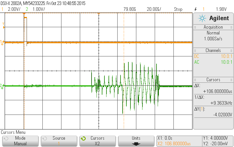
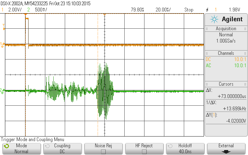
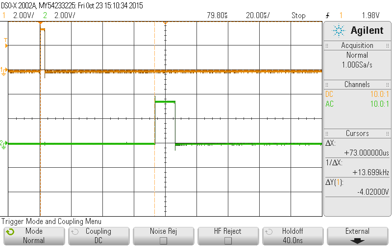
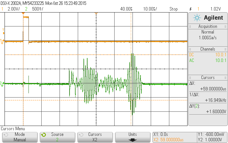
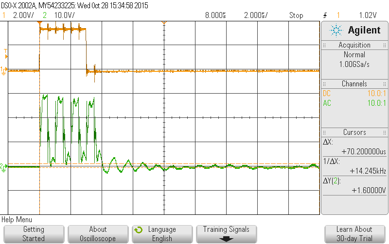
When I monitored the signal, there is strong first echo at 80 uS all right. 

1480*(80*10^-6)*100/2 = 5.92 cm

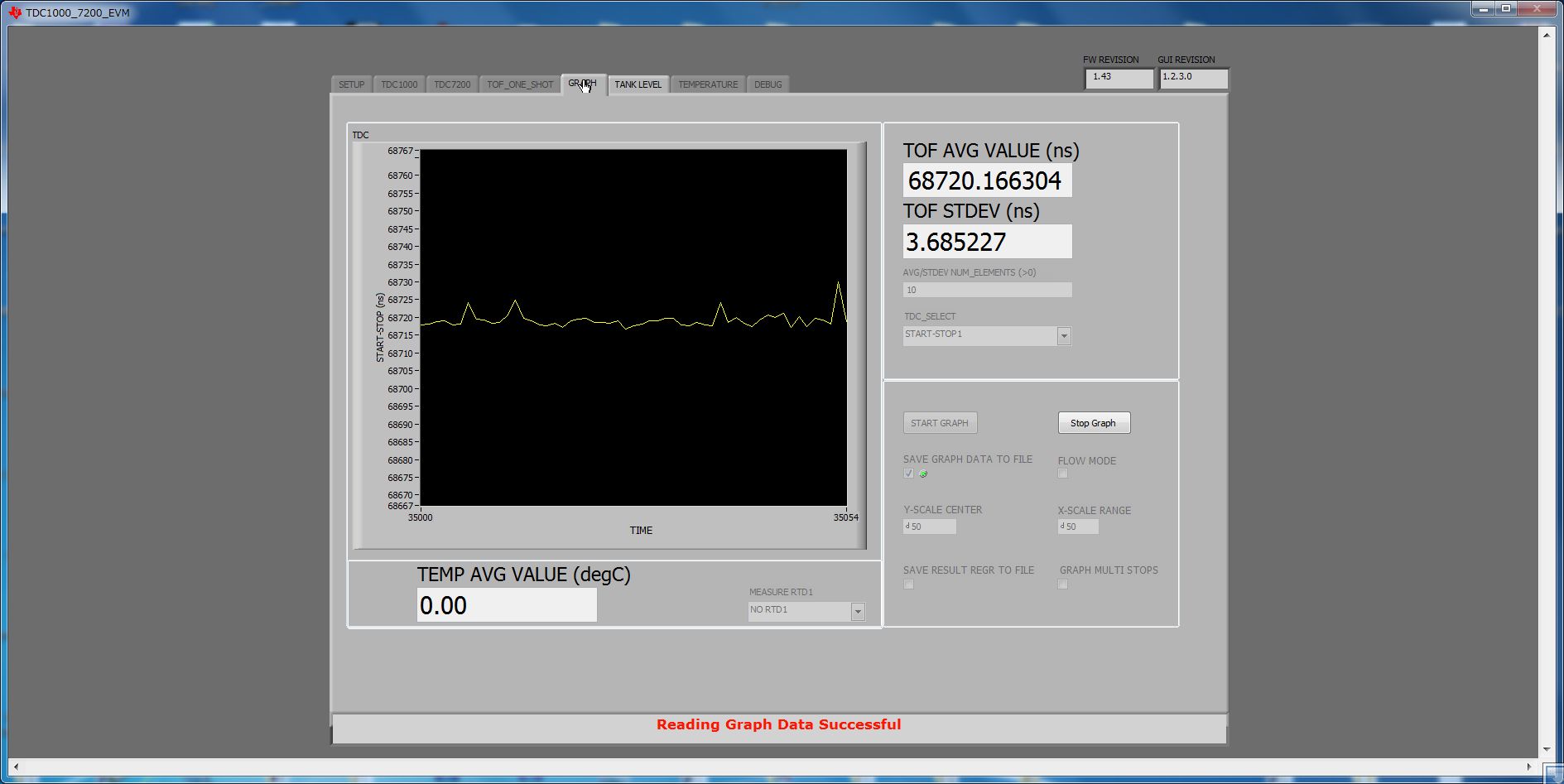
But GUI measured the 160 uS --- the next echo, I think. 

Is there any way to measure the 1st echo ?

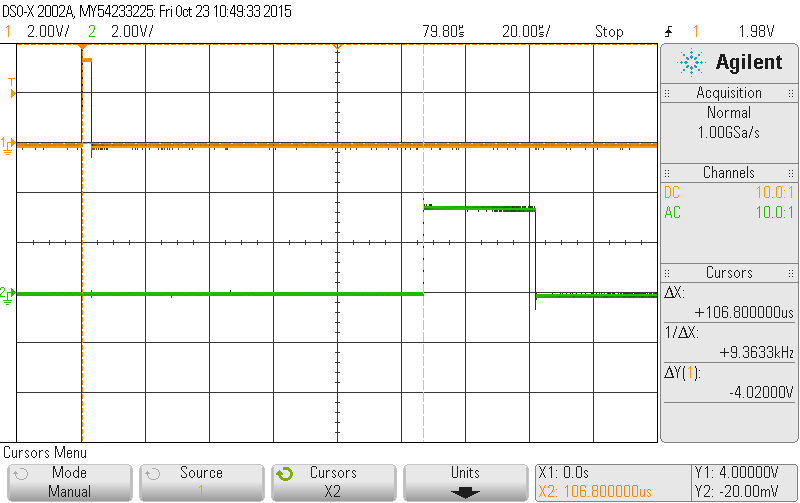
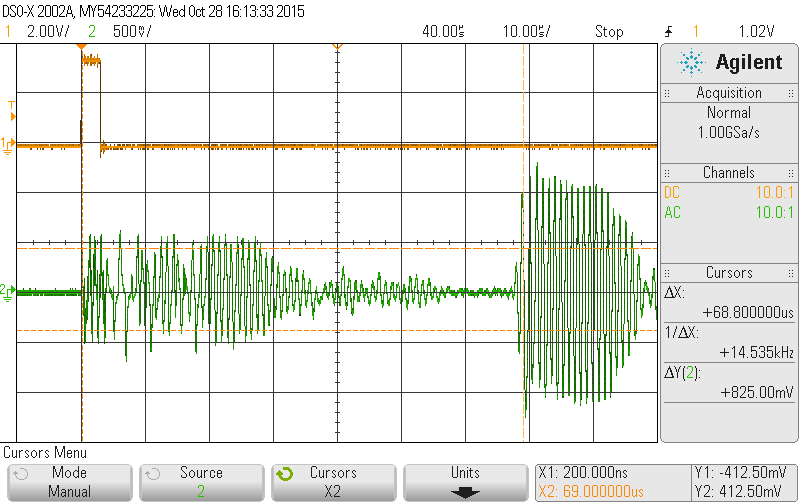
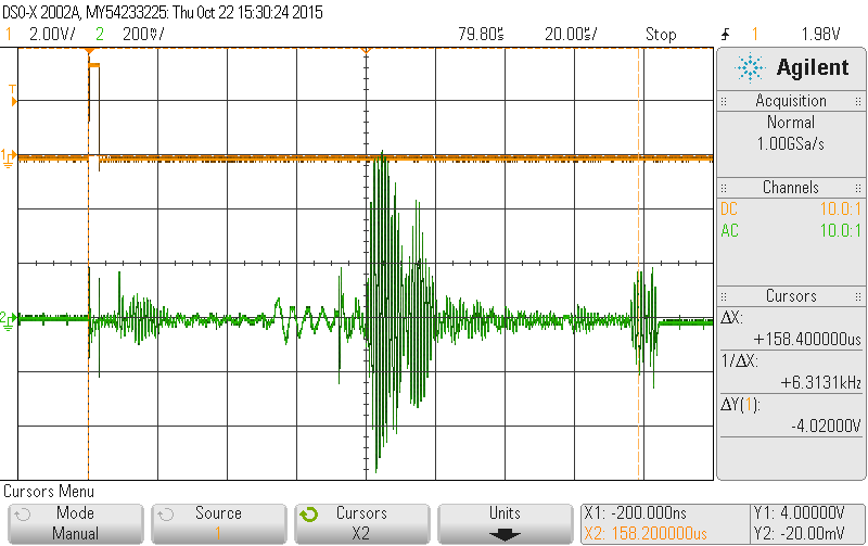
(1) Oscilloscope waveform
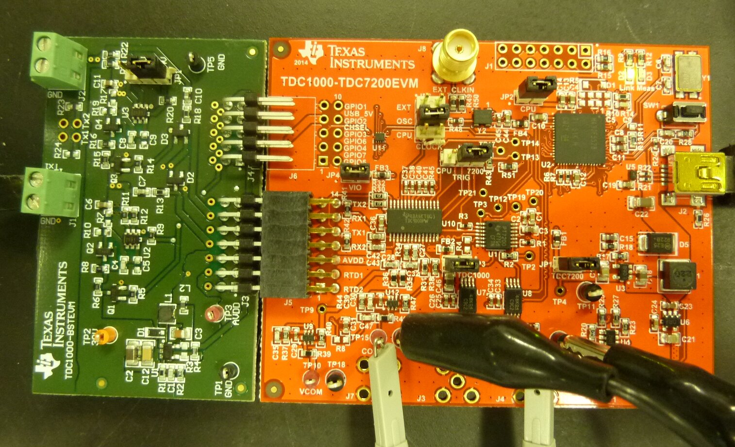
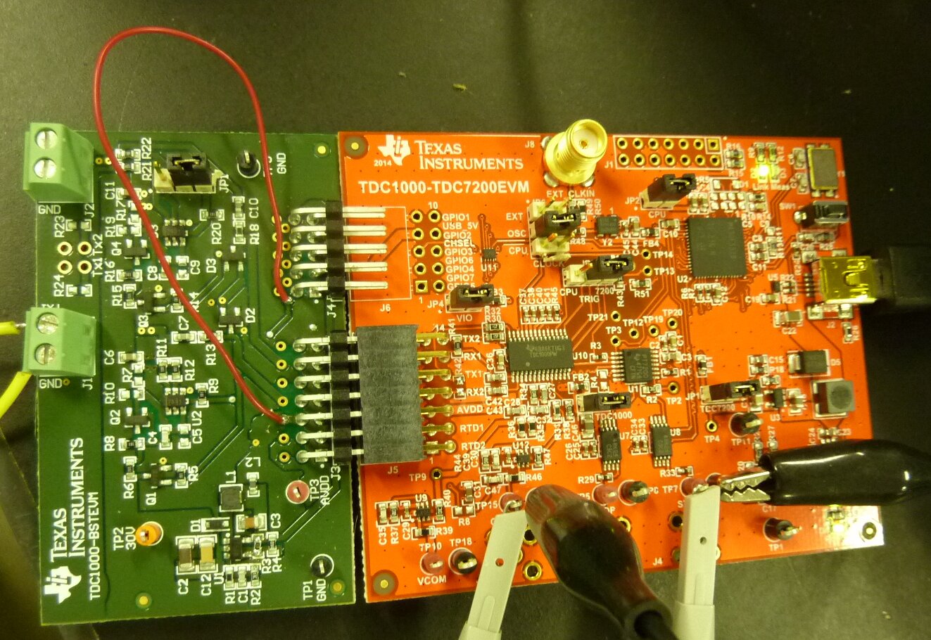
(2) Setup

(3) TDC1000 setting

(4) graph

(5) tank level

  • Koyo,

    A few questions first:

    1. what frequency is your transducer?

    2. What are your measuring requirements (min/max height)?

    3. Can you send a scope picture that includes your Stop signal as well?

    I believe the big issue is your Autozero time and your blanking.

    Set your Clock Rate reg to 0x00 will reduce the "autozero blanking" to ~32us so it will detect the first echo.

    Also increase your Vthrshold to 410mv.

    TDC1000_Config0                         08
    TDC1000_Config1                         41
    TDC1000_Config2                         00
    TDC1000_Config3                         05
    TDC1000_Config4                         5F
    TDC1000_TOF-1                           A3
    TDC1000_TOF-0                           FF
    TDC1000_Error_Flags                     00
    TDC1000_Timeout                         00
    TDC1000_Clock_Rate                      00
    TDC1000_Conts_Trigger                   00
    TDC7200_Config1                         00
    TDC7200_Config2                         00
    TDC7200_Interrupt_Status                00
    TDC7200_Interrupt_Mask                  00
    TDC7200_Coarse_Cntr_Ov_H                FF
    TDC7200_Coarse_Cntr_Ov_L                FF
    TDC7200_Clock_Cntr_Ov_H                 FF
    TDC7200_Clock_Cntr_Ov_L                 FF
    TDC7200_Clock_Cntr_Stop_Mask_H          00
    TDC7200_Clock_Cntr_Stop_Mask_L          00
    TRIGGER_UPDATE_FREQ                     0001
    TDC_AVG/STDEV_NUM_ELEMS                 000A
    SAVE_GRAPH_DATA_TO_FILE                 00
    FLOW_MODE_SELECT                        00
    Y-SCALE_CENTER                          0032
    X-SCALE_RANGE                           0032
    MEASURE_RTD1                            00
    SAVE_RESULT_REGR_TO_FILE                00
    GRAPH_MULTI_STOPS                       00
    TDC_SELECT                              00
    TEMP_RTD_SELECT                         00
    TEMP_RTD_MODE                           01
    TEMP_AVG/STDEV_NUM_ELEMS                000A
    SAVE_TEMP_DATA                          00
    GRAPH_YMAX_DATA                         00000000004C4B40
    GRAPH_YMIN_DATA                         0000000000030D40
    TDC1000-HV_DRV_EN1                      01
    TDC1000-HV_DRV_EN2                      00
    HV_DRV_EN1_Period                       0028
    HV_DRV_EN2_Period                       001E
    ENABLE_POWER_CYCLE                      00
    CLK_FREQ_(1-16MHz)                      2.000000
    CLK_SOURCE_SEL                          02
    CPU_CLK_FREQ                            0C
    CPU_CLK_EN                              01
    TDC1000-HV_BST_PWR_EN                   01
    HV_BST_PWR_EN_Period                    0000
    FWD2REV_FLOW_DELAY                      0000
    TDC1000-IMPE_MATCH_EN                   00
    ENABLE_UART_STREAM                      00
    ENABLE_MSP430TIMER_TDC                  00

    I'm attaching a register file that can be loaded to set all these values.

    Best regards,

  • Dear Matthew Minasi, thank you very much for the configuration file "TDC1000_Kobe_Setup.txt"

    I loaded your configuration file and tried again.

    I added my answer to your question below.  

    1. what frequency is your transducer?   1MHz

    2. What are your measuring requirements (min/max height)?    min : 20mm   max : 2000mm

    3. Can you send a scope picture that includes your Stop signal as well?   I get the picture with your configuration file below.

    1) START and COMPIN_OUT

    2) START and STOP

    I believe the big issue is your Autozero time and your blanking.

    Set your Clock Rate reg to 0x00 will reduce the "autozero blanking" to ~32us so it will detect the first echo.

    Also increase your Vthrshold to 410mv.TDC1000_Kobe_Setup.txt

    I'm attaching a register file that can be loaded to set all these values.

    3) Setup

    4) TDC1000

    5) Graph

    6) Tank

    I still can't get the signal at 6cm.

    What should I do ?

    Hope to receive some answer soon !

  • I tried the same experiment with TDC1000-TDC7200EVM today as the reference.

    Default setting is fine and I can measure the first echo all right. 

    With the 8MHz clock, TDC1000 works all right. 

    So, there seems to be some limitation when I use the 2MHz CPU clock on TDC1000GASEVM, I think. 

    (1) START - COMPIN_OUT

    (2) START - STOP

  • Koyo,

    The minimum Autozero @ 2Mhz is 32us. When you increase the input clock the timing resolution increases accordingly.

    See attached doc.

    Best regards,kobe.docx

  • LDC1000-GASEVM's limitation seems to be much longer than 32uS, I feel.

    By the way, I tried one more test. 

    Connecting the high voltage drive board of LDC1000-GASEVM (TDC1000-BSTEVM) to the LDC1000-LDC7200EVM.  

    ( Mixture of two EVMs ---  LDC1000-LDC7200EVM's 8MHz clock and LDC1000-GasEVM's 30V drive board)

    I think there is no problem with this combination. 

    I can measure 59uS echo = 4.366 cm water level in the tank with them!

    This time, the second echo at 59uS is the real one. 

    The first echo at 35uS seems to be from the polycarbonate case. 

    (photo)

    (scope)

    (graph)

    (tank)

  • I checked the waveform at J1 pin-1 = Ultrasonic Transducer voltage.
    The voltage is much lower than expected.

    It is not 30Vp-p, only 1 Vp-p.

    I compared the TDC1000-GASEVM and TDC1000-BSTEVM Kit User’s Guide 15 TDC1000-BSTEVM schematic Figure 27 with the real board.

    There are some differences.

    R5 = 51.1k is not there. Nothing was soldered.
    So, TP2 is not 30V. TP2 is only 3.6V.

    R10 is not connected.
    So, Vdd1 is not 30V.

    Maybe the Ultrasonic Transducer is actuated from Rx2 ( which is connected to Tx1 ) through R13=300 and C7=300pF.

    That's why the received signal is so weak.

    I'll add these missing parts tomorrow to drive the ultrasonic transducer at 30Vp-p.
  • I modified TDC1000-TDC7200EVM board --- removing R42=0 ohm. 

    I also modified TDC1000GasEVM's BSTEVM board --- R3=12k ohm (not used), add Jumper wire between J4-1 and TP3=AVDD.

    Now, I can transmit 1MHz 30Vp-p signal all right.

    (photo)

    (scope Tx signal 1MHz 30Vp-p)

    (scope : start and comp-in 68.7uS)

    (graph 68.7uS)

    (tank 5cm)

    ( after adding some more water up to 20cm )

    (graph)

    Now, I need to write some software to try the water level up to 100cm and 200cm in near future. 

  • Koyo,

    The TDC1000-7200 EVM isn't shipped to interface with the BSTEVM without making modifications  to it first.

    As you discovered  R41 and R42 will need to removed. Also C42 and C43 need to be removed and replaced with 0 ohm resistors to make the TDC1000-7200 EVM work properly the the BSTEVM.

    Jumping J4-1 to VDD will reduce your echo size and isn't necessary as this is controlled by firmware driven on the MSP430. You will need to the the Boost Supply set the HVEN duration however as described in TDC1000-BSTEVM User's Guide. I'm attaching a version for you're convenience.

    Best regards,

    SNIU026_updated_sch.pdf

  • Thank you very much!

    I checked the SNIU026_updated_sch.pdf you sent me.  

    The reason why I put the Jumper (J4-1 to Vdd) is that there is no J6 on the TDC1000-TDC7200EVM. 

    (please check the photo below)

    I don't have the 10-pin female type angle connector which is needed as J6 on the TDC1000-TDC7200EVM to connect to J4 on the BSTEVM. 

    It'll take somedays to buy it from Digi-key as I need to import it to Japan.  

    So, there is no connection between J4 (BSTEVM) to J6 (TDC1000-TDC7200EVM) now. 

    So, I put the Jumper wire instead now. 

    Anyway, I think I have enough information to go on the design. 

    Thank you very much again for your help!

  • Koyo,

    Your welcome. 

    If you are ok with jumper wires you'll want to jumper the VDD1_EN connection (J4-p1) to JP4-p1 instead of to VDD. It will give your receive circuit 3-4 times more sensitivity. This signal controls the power to the UCC27531 and disables it during the "receive" time. If it is always enabled it loads the transducer with 110 ohm to GND which attenuates the receive echo. I notice you installed R3 on the BSTEVM which is the right choice.

    Best regards,