This thread has been locked.

If you have a related question, please click the "Ask a related question" button in the top right corner. The newly created question will be automatically linked to this question.

TMP421 I²C Communication Problem

Other Parts Discussed in Thread: TMP421

Hello,


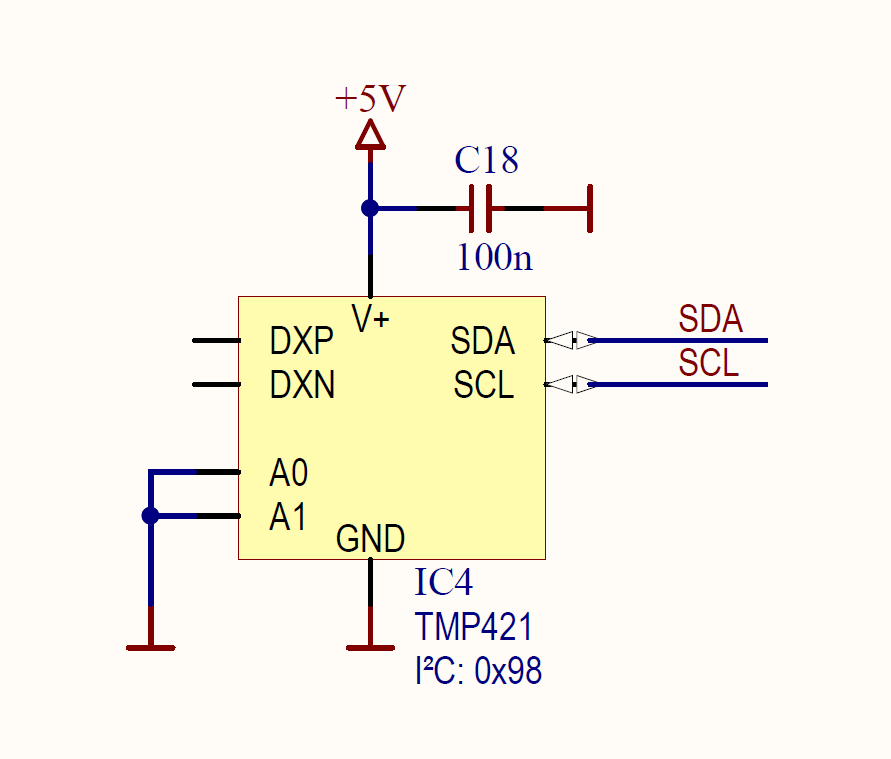
we see a serious problem when trying to communicate to the TMP421 Temp sensor via I²C with our Atmel 32Bit Controller.

System Voltage: 5V

Clock Frequency: 400kHz (also tried 200kHz)

Most interesting: when using low PullUp values (2k2 / 4k7) it doesn't work. with 10k it's working sometimes, but with 22k and very long rise times it is working.

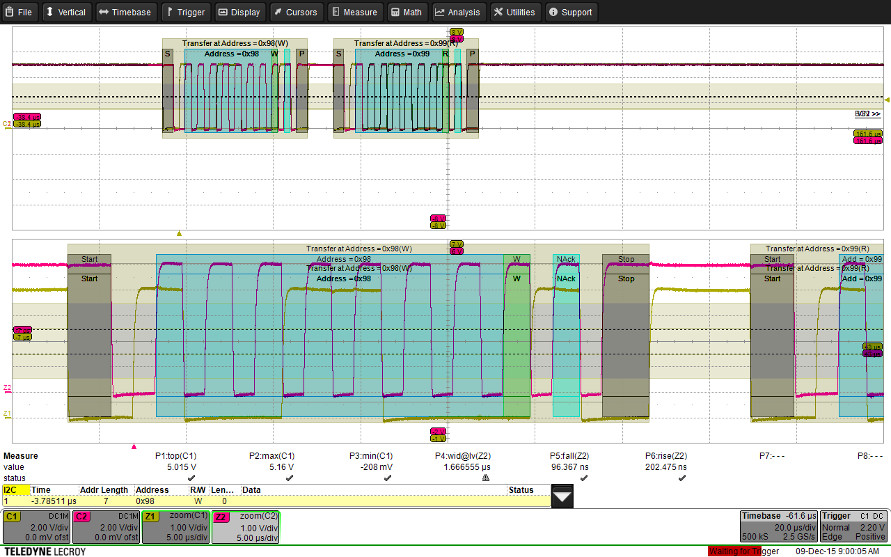
When checking with the oscilloscope I cannot see any problem with the I²C Protocol or any timing issues. The oscilloscope is decoding correctly everytime!

You can see that risetime is in specification with the TMP421 values...

Any help will be appreciated!

  • Hi Benjamin,

    I worked with Atmel MCU in the past, but as I recalled the maximum supply voltage for VDDIO should be around 3.6V. I could be wrong. Not sure which Atmel MCU series you are using in your system. Since you stated that the system power supply is 5V, you might need a level translator or level shifter for all your communication lines. Without the level shifter, you could run into inaccurate timing issue because of unsteady of rise and fall time.

    Please confirm if you have the Atmel MCU that is supported up to 5V power supply.

    Aaron
  • Hi Aaron,
    thanks for your hint, but the MCU is a 5V type (8Bit AVR run up to 5V, the XMega types with 3.3) but the AT32UC3C1512 runs with 5V "again".

    Do you see a Timing or "Shape" issue from the scope screenshot above? In my opinion it looks like a good signal. But the TMP421 only acknowledges it, if I use 10-22k pullups and the rise time equals the high-duration of clock!
    Benjamin
  • Hi Benjamin,

    I have reviewed your attachment. Before I can further comment, would you please confirm the following question below?

    1. What do you connect the A1 and A0 pins to (VDD, GND, or floating)?

    Aaron

  • Hi Benjamin,

    Do you have any updates?

    Aaron

  • Hi Aaron,

    sorry, I accidentaly turned off the eMail notification.

    Both address lines are connected to GND.

    Benjamin

  • Hi Benjamin,

    I will be taking over this thread from Aaron. Let me ask some more questions regarding this:

    1. Are there any other IC's connected to the I2C bus?
    2. Is it possible to increase the hold time on SDA?

    -Michael Wong
  • Dear Michael,

    no, there are no other Parts connected via I²C. The trace length is about 10mm with <0.7mm difference.
    There are some parameters inside the AVR which might tweak the timing, but thought I²C is latching during clock high, not the falling edge?

    Benjamin

  • Hello Michael, Aaron,
    IMHO the TMP421 behaves not as specified by the datasheet.
    According to our oscilloscope, the fall time is about 95ns, but the sensor needs an additional SDA hold time to work.
    Datasheet states that ONLY below 20ns the hold time must be increased (otherwise Thddat=0ns) - but this seems to be also the case if the rise/fall time is about 10times slower.
    Nevertheless, solution was possible using a tweak in the AT32 TWI register CWGR setting the CWGR.DATA to a value higher than 4!

    Benjamin
  • Hi Benjamin,


    On page 20 of the datasheet, the data hold time specification of 0ns and footnote (1) is incorrect. It is a known issue and we are in the process of making these changes. Thank you for your patience.

    It is good news you got the TMP421 to work by tweaking the registers. Is there anything you need help with?


    -Michael Wong