This thread has been locked.

If you have a related question, please click the "Ask a related question" button in the top right corner. The newly created question will be automatically linked to this question.

FDC1004EVM and TIDA-00317

Other Parts Discussed in Thread: TIDA-00317, FDC1004EVM, FDC1004

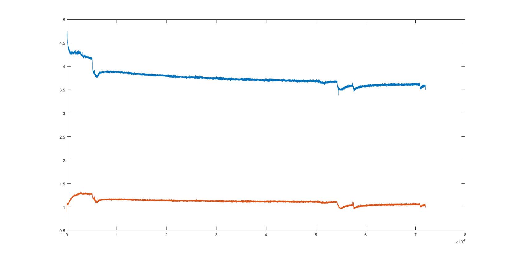
Hello, I have replicated the TIDA-00317 circuit and with the FDC1004EVM i would measure the liquid level. To see the capacitance I use the program FDC1004EVMGUI.

my problem are that the capacitance change everyday at the same level liquid and i don't understand why.
I thought the problem was the FDC1004EVM that I plug and unplug, but I tried to save the data for 20 consecutive hours and they change the value continuously
the capacitance stat whit 4.2pF (for 50mm of liquid), 10 hours late the vale are 3.8pF, and at the end the value are 3.5pF.

i don't understand the reason for this difference

  • Hello,

    Thank you for contacting TI. We will get back to you during our group's normal business hours (Mon-Fri, PST).

    Regards,
    Yibo
  • Hi Federico,

    There's a couple things that could cause this. I have few quick follow up questions to help narrow it down:

    1) This usually happens due to a change in the baseline capacitance. http://www.ti.com/lit/an/snoa925/snoa925.pdf note that equation 2 of that app note uses Clevel(0) and Rcl(0) (when not using environmental sensor) as an offset to determine liquid level height. If this value changes then you will get an error in your measurement. This measurement is nothing more than the Clevel and Crl when the tank is empty. Do you notice this value to change with time as well?

    2) How did you recreate the TIDA-00317 reference design? Was it on a PCB or did you use copper tape or something else flexible? The most common thing to change the baseline capacitance is mechanically flexing the wires on the Clevel and Crl lines. To achieve best performance and accuracy having the sensors and the FDC1004 on the same PCB will avoid this.

    3) my only other thought is some kind of temperature drift, is your temperature changing a lot over this time period?

    Best regards,

    Nate

  • Hi Nathaniel Enos,

    thanks for the reply.

    1) the problem are that it's difficult set-up the sensor because i ave everyday at the same level of liquid different value, and this camghe my mesure level if i use the reference of pass day.

    2) I had realized the TIDA-00317 whit a milled Arlon25. For the gerber file i had used  those on this page under Design Files.
    the TIDA and the FDC are attached whit a 5Cm flat cable.

    3)At the first moment i have think that temperature drift can change the value, but the variance of temperature are maximum 3°C

  • Hi Federico,

    It's my pleasure. So from your comment 1) it sounds like it is the baseline capacitance that changes every day which is leading to your change in total capacitance.

    I believe the main reason for change in capacitance would be due to movement of the 5cm flat cable going from the TIDA to the FDC board. It's good to hear that your sensor is made on a PCB. Are these boards mounted to anything so that the wire does not move? or is your test fixture moved at all during this time?

    I don't suspect the temperature to change the capacitance by too much sense you have reference sensors on your board as well. Those should move together with temperature drift and cancel out, especially with only 3 degrees change.

    Best regards,
    Nate
  • Hi Nathaniel,

    i don't know if the cable moves, i don't think that its possible, for the test i had put the cable in the table and in the room no one has entered.

    i had tried 2 times to put the capacitance and in the first case the capacitance ave decrease the value, in the second case have increase a lot at first and increasing a little bit in a second time.

    1.case

    2.case

  • Hi Federico,

    How did you mount the sensor to the container? Can you please post a couple pictures of your setup so we can have a closer look?

    Regards,
    Yibo