Because of the Thanksgiving holiday in the U.S., TI E2E™ design support forum responses may be delayed from November 25 through December 2. Thank you for your patience.

This thread has been locked.

If you have a related question, please click the "Ask a related question" button in the top right corner. The newly created question will be automatically linked to this question.

FDC1004 SNOA925 experiment question - OoP Liquid Level Technique

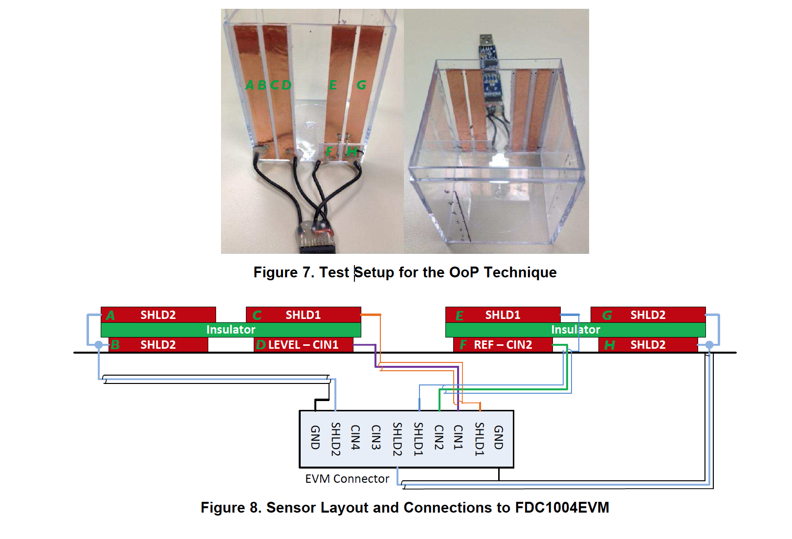
This photo (figure 7) does not seem to match the Figure 8 layout. I am expecting them to match. We tried replicating the experiment but did not have success. Can someone please tell me where the discrepancies lie?

  • Hi Malcolm,

    The photo may not be very clear, but the setup matches with the schematic. Those black wires in the photo are shielded cables, which may not be immediately obvious.

    This reference design also has more information:
    www.ti.com/.../TIDA-00317

    Regards,
    Yibo
  • Thanks for the reply Yibo. I understand the shielded wires but I do have other questions. Using my lettering scheme below:

    B, D, F, H would be closest to the liquid being measured. Insulation would be between A/B, C/D, E/F, G/H. Why does it appear that E and F are connected? And is H the same size as F?

    Thanks

  • Hi Malcolm,

    E and F are not connected. They are actually separated by small piece of scotch tape to provide insulation. F is very short, so the shield from that wire is attached just above it to E, while the core is soldered to F. Then they are both hot glued, so it's tough to make out what's attached to what with that picture.

    and yes, H and F are both the same size. Everything is kept symmetrical to maximize performance.

    Let us know if you have any additional questions!

    Nate

  • Okay, thank you. I think I have it now. Will try again tomorrow. I appreciate you taking the time to explain it to me.

  • It's our pleasure!

  • Nat, If you could verify one more thing, please. In the photo, the E and G shields actually look adjacent to the liquid and F and H look to be exterior to the shields. I assume this is an optical illusion. F & H are actually closest to the liquid. Sorry for being so dense. Just want to verify.

  • Malcolm,

    You're not being dense at all. I agree that the tape makes it hard to tell which order the copper strips are in. Rest assured, the sensors are always closest to the liquid and the shields are always on the outside of the sensors to add directionality to their sensitivity (we want the sensors field to face in towards the liquid and not be sensitive to external noise).

    Thus, F and H are indeed closest to the liquid, with the shields E and G being exterior to the sensors.

    Hope this helps clear that up!

    Nate