This thread has been locked.

If you have a related question, please click the "Ask a related question" button in the top right corner. The newly created question will be automatically linked to this question.

Interpreting TDC1000-TDC7200EVM UART Data w/ Arduino

Other Parts Discussed in Thread: TDC1000, TDC7200

Hello,

I'm trying to access time of flight data external to the GUI using the EVM's UART and display it like in the following thread:

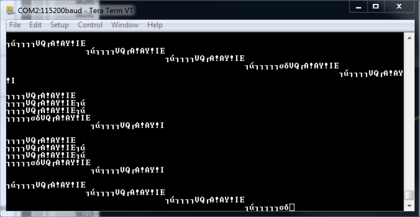
I'm confused on how to interpret the data in my program (I'm using an Arduino) to deduce the time of flight from the transmitted bytes. I'm getting the bytes to display in my program but am unsure of how to arrange the bytes to get the full precision like in the above thread.

Thanks!

  • Andrew,
    The TDC1000-TDC7200EVM firmware source code zip is available as part your GUI installation folder: C:\Program Files (x86)\Texas Instruments\TDC1000_7200EVM\Firmware.
    Please look at the source code file "tdc7200_calculation.c", lines 91-97. Basically, there's a for loop that shows the exact data and values being printed out to the outString buffer. All the start2stop values calculated and sent out are in ns.
    You can also connect a terminal emulator like Tera Term and see the exact data coming out.
    Thanks,
    Vishy
  • Hey Vishy,

    Works perfectly! Thanks for the help. 

    Andrew

  • Hi Vishy,

    I am having trouble getting getting correct data out of the UART of my TDC1000-TDC7200EVM. I am getting  solid readings in the GUI. I have connected the GPIO pins 3 and 4 to my serial-to-USB port and I am using TeraTerm with 115200 baud. I just get garbage characters. Out of curiosity I hooked up my Saleae digital analyzer for serial async protocol to the GPIO pin 4. It does capture correctly though it reports an auto baud detection rate of 115900. I have tried everything I can think of including different USB-toSerial devices. Any thoughts?

    Thanks,

    Bob

  • Bob,
    The UART baud is based on the MSP430 system clock (24MHz crystal on the TDC1000_7200EVM). Is anything changed on the board?
    You mention GPIO pin 4. In the schematic, it looks like pin 4 is MSP430 UART RX. You should look at GPIO3?

    Another question: In the Debug Tab there's a "Enable UART Stream" option. Did you enable it?

    Thanks,
    Vishy
  • Vishy,

    Nothing is changed on the board. I should have said my Saleae analyzer was connected to GPIO3 which is pin 6. It totally gives the correct data stream, no problems. Yes, the stream was enabled on the Debug page. The problem is with the serial-to-USB that is connected to TeraTerm. That gives me garbage, I will paste my settings dialogs for TeraTerm again. It appears you can't just cut and paste images.

    Bob

  • Bob,
    I use the FTDI cable TTL-232R-3V3.
    Thanks,
    Vishy
  • Would anyone mind sharing their arduino code here? At least the parts that are relevant would be great. Has any written a library?
  • Jeff,

    You can find the TDC1000_TDC7200 EVM firmware source code zip under the GUI install folder
    C:\Program Files (x86)\Texas Instruments\TDC1000_7200EVM\Firmware

    Of course, this is for MSP430 not Arduino but can give you a starting point. Especially, you should be able to see the SPI setup and also see how the registers are set up, results are read and TOF is computed.

    Thanks,
    Vishy