This thread has been locked.

If you have a related question, please click the "Ask a related question" button in the top right corner. The newly created question will be automatically linked to this question.

The FX2 Firmware about OPT8241-CDK

Other Parts Discussed in Thread: OPT9221, OPT8241

Because the OPT8241-CDK is always at 'PREVIEW' statues,I can't purchase the module at the moment, so I make a board by myself that reference to sbac138(www.ti.com/.../toolssoftware, but not provide the FX2 firmware, so I write some codes for the FX2
After load the TFC (OPT9221) firmware, I put FX2 at Slave FIFO mode, but I can only read a small amount of data from the TFC.

I would like to ask you some questions about the trouble as below. 
a: Could you provide the FX2 Firmware of the OPT8241-CDK EVM.
b: I configured the Register 0h (7.6.2.1 ) to reset the TFC register and Register 80h( 7.6.3.11) to start the data flow,can you give me some advice about it.

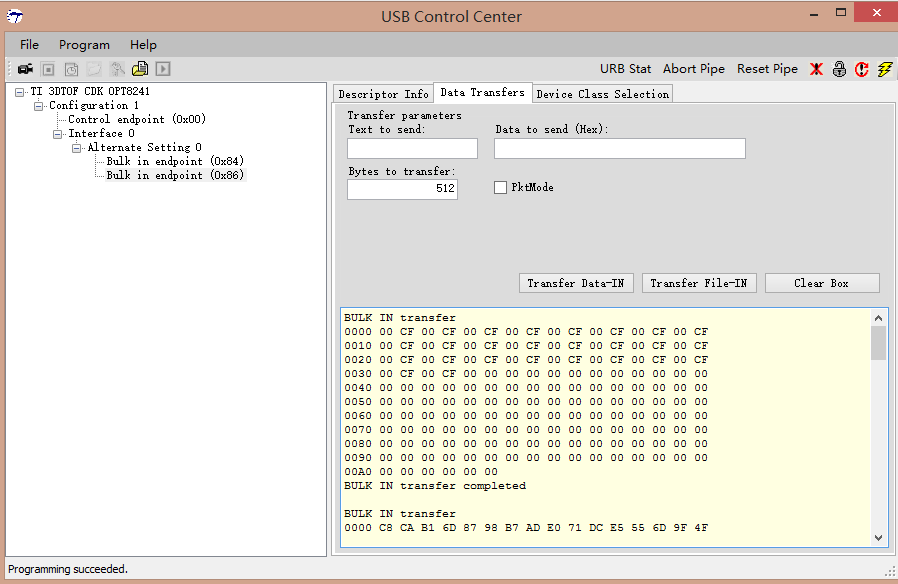
After four data transfer, The TFC stop write data. The below images show the issue


thanks,best regards.

  • Hi,

    Sorry for the inconvenience. The FX2 firwmare on the OPT8241 CDK is specially customized to initialize the power supplies. The custom FX2 binary to be used on OPT8241-CDK will appear on the web by the end of this week. Also, the CDK will be available for purchase very shortly (~in a week's time). Please watch out for change on this page - www.ti.com/.../opt8241-cdk-evm

    Regards

  • Hi Bharath Patil,

    Thanks for you quickly reply.

    I have downloaded the FX2 firmware to our own board, and we see the depth data by Voxel Viewer. But I want to code the FX2 program by myself, there are some questions to ask you:

    Q1. I just need to get continuous data, which registers need to be configured on TFC.

    Q2. When the TFC had configured as Generic parallel mode, the corresponding need for FX2 configured as slave fifo mode?

    Q3. In the next period of time, FX2 firmware and Voxel Viewer software whether open source? How do we get the source code? If developer can get the source code, it will be accelerate products to market.

    Q4. After I update the TFC firmware by Voxel Viewer-0.7.0, the TFC does not work. By reading back the EEPROM data and compare to OPT9221_0v23.tie, I found there are some wrong in EEPROM data ,So I had to use a EEPROM programmer to update the TFC firmware.

    Regards
  • Hi minRiver,

    A1: if you just want to start outputting some data, you only need to program tg_dis=0.
    If you want to also get a test pattern to check the output interface, you can set phy_test_enable = 1. This will output a continuous 8-bit ramp pattern starting with two 0s (i.e., 0, 0, 1, 2, 3, ... , 254, 255, 0, 1, 2), and the pattern will restart for every frame.

    A2: We always use the FX2 in slave fifo mode. We use the ready signal to indicate to OPT9221 that the fx2 is able to accept more data.

    A3: VoxelViewer is just a simple GUI around VoxelSDK. All the initialization and configuration APIs are available in VoxelSDK and VoxelViewer uses only these APIs
    VoxelSDK is already open sourced and the source code is here:
    github.com/.../voxelsdk

    For FX2 firmware, we plan to release the source code shortly.

    A4: Could you please confirm that you are using the OPT9221_0v23.tie file from here?
    www.ti.com/.../sbac142

    Best Regards,
    Anand
  • Thanks for you quickly reply.
  • Hi,

    I purchased OPT8241-CDK has arrived, I intend to refer OPT8241-CDK add some new features, but I found VoxelSDK must meet FX2 firmware to work, So I want ask what time release the source code of FX2 firmware,that will very beneficial for my development.

    Best Regards
  • Hi,

    The I2C transactions for control as well as the data acquisition is already exposed in Voxel-SDK. Is there a specific reason for which FX2 source will be required? Reprogramming the FX2 with a custom firmware is not recommended as it will void the laser safety on OPT8241-CDK.

    Regards

  • Hi,Bharath Patil

    Sorry, I did not express my words clearly. I promise that we will not take OPT8241-CDK as our own commercial products. We intend to design a product by ourself which is similar to Kinect 2.0. In our plan, we will add a RGB camera by replacing FX2 with FX3. I hope to require the FX2 source code as a reference work. Thanks very much.
    Regards
  • Hi,

    The main issue is the laser safety. Can you mail us at ti-3dtof@list.ti.com?

    Regards
  • Hi, I'm in the same situation here. We are building a custom board and we will connect the controller directly to our on board processor. We don't want to implement an FX2 as it has no added value. But understanding what sequence is programmed in the FX2 for power rail initialization and register would save us time.


    Also Voxel SDK code is huge and needs a lot of reverse engineering to understands the design decisions that were made. Is it all based on predefined video modes that get triggered by the UVC or USB streamer or does the library set specific registers?

    This is why getting the FX2 source code would be useful.

    I understand the issue with laser safety, I by chance have expert here on the subject.

    Regards

  • Hi,

    For custom boards based on OPT8241+OPT9221 (Tintin chipset), there is an example firmware source code here -
    github.com/.../fx2-reference-firmware

    Note that the reference firmware source won't work on a regular OPT8241-CDK-EVM (by design for laser safety, it may brick the CDK and render it unusable). Programming a custom FX2 firmware on OPT8241-CDK-EVM amounts to tampering and is not recommended as it voids laser safety.

    Regards
    Bharath
  • Hi

    We are also trying to control the OPT8241-CDK with an external embedded system. Our inmediate goal is to get the information using the parallel output available in the external debug connector.
    What we want to do is to be able to start the camera without connecting it to the pc, using the I2C interface to configure the OPT9221 and getting the data from the CMOS output.
    Is there any way to be independent from the voxelSDK (or Voxel Viewer) and be able to use the EVK controlling it via the debug connector?

    Thanks

    César Carballido
  • Hi César,

    All relevant pins are already brought out to the J2 debug connector. There is no need to use the VoxelSDK if you don't want to.

    However, all initialization must then be done by you independently.

    To start with, you can refer to the reference FX2 firmware source for PMIC initialization:
    github.com/.../main.c
    and
    github.com/.../pmic.c

    and for OPT9221, you can refer to the board initialization sequence from here:
    github.com/.../TintinCDKCamera.cpp
    and
    github.com/.../ToFTintinCamera.cpp

    You may want to isolate the FX2 chip from driving the I2C bus.


    Warning: The CDK-OPT8241-EVMs use lasers for illumination. The debug connector is deliberately not populated on these EVMs for laser safety compliance. If you modify the board to use the debug interface, then our laser safety certification is void and you are responsible for ensuring safety while operating this EVM.

    Best Regards,
    Anand
  • Hi Anand

    Thanks for the links to the software. I started using them and those will save me a lot of time to develop my own application.

    Although I have a doubt about the pmic. Inside pmic_init functions there are references to a variable, hw_init, that is loaded according to an EEPROM connected to the FX2. In the main.c file this EEPROM is referred to with add=0x51. In the schematics I´ve found a 24AA16 EEPROM connected to the FX2, but according to the datasheet of this memory there is no way its addres could be that one.

    What I actually want to solve is how to know which is the hw_version of my kit, in order to perform the right pmic init. Is there any way to do it by just looking at my OPT8241_EVK kit? Can I reproduce this EEPROM read as in the described code and get the right result?

    Thanks

    César
  • Hi César,

    The 24AA EEPROM should have been the 24AA512. It is correct in the BOM but not updated in the schematic.
    It's 7-bit I2C slave ID is 0x51 and it is the boot EEPROM for the FX2.

    The hardware version for all released CDKs is version 2. All version 1 boards had green colored PCBs while the version 2 boards have black. You should have a version 2.

    - Anand