This thread has been locked.

If you have a related question, please click the "Ask a related question" button in the top right corner. The newly created question will be automatically linked to this question.

FDC2214 Drift over time

Other Parts Discussed in Thread: FDC2214EVM, FDC2214

Hello,

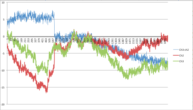
I am working with the FDC2214EVM and am noticing quite a bit of drift over time and was wondering what can be done to reduce the drift.  I have my EVM mounted in a shielded enclosure and I am using a nice clean function generator.  I even leave the room and remote into the computer to do the measurements to control any stray human capacitances.  My EVM stays in the enclosure and the INA channel is wired to a connector on enclosure.  I disconnected my sensor and capped the connector on the enclosure for the following drift measurements.  Attached is a plot of several measurements over 5 minutes and the drift is up to 50 fF.  The full range of my sensor is <130 fF so this drift can obscure a big portion of the range.  

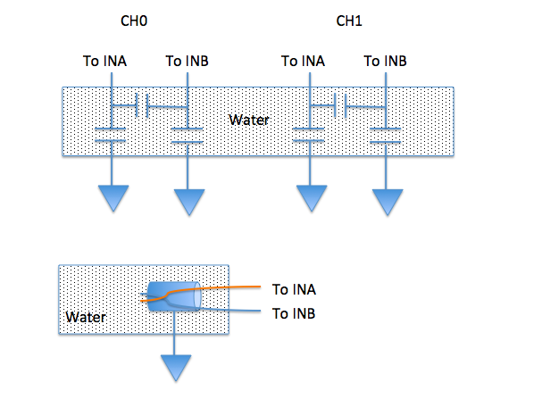
This drift does not seem environmental so I don't think I can go with a differential configuration.  Plus, do to design constraints, I can only use a single-ended configuration.

Thank you!

  • Hi Jay,

    This is likely due to temperature fluctuation in the system. Such slow drift can be compensated for in software algorithm. If your application is proximity detection, you would be looking for a much faster change than the baseline drift. For more sophisticated measurement, you may consider using this algorithm.
    e2e.ti.com/.../capacitive-sensing-simple-algorithm-for-proximity-sensing

    Regards,
    Yibo
  • I am seeing a similar issue with drift.  I need a differential signal between channel 0 and channel 1, and another between channels 2 and 3 (i.e., one signal is ch1-ch0, and the second signal is ch3-ch2).  The sensor is comprised of two wires twisted together, one connected to INA and the other to INB.  The twisted pair of wires is inserted into a grounded tube.  The tube is immersed in water.  The attached picture shows the physical implementation and the logical circuit equivalent.  Total capacitance of the sensor is ~15pF

    My signal is a slow rising one, so I may not be able to use the SW first derivative integration algorithms to find the signal in a drifting baseline.  I've attached two plots one that shows a pretty good correlation between channels, and one where the channels are drifting.  Even in the drifting case, the two channels do show a high degree of correlation.

    Any ideas why this might be happening?  I have been looking at this problem for 6 months now and am out of ideas.   The insulation material on the wires is PTFE (Teflon) which is not absorbing water.  Any ideas would be very much appreciated.

    Bill Dunham

  • Hi William,

    The drift is likely due to small temperature fluctuations. For example, even the NP0/COG capacitor has a rating of +/-30ppm/degree C. Try to minimize any parasitic capacitance along the signal path from the sensor to the FDC. Also, we generally recommend using a ratiometric approach to measure capacitance, as explained in the application note below. As you have already seen, the channels show strong correlation for such environmental effects.
    www.ti.com/.../tidu736a.pdf

    Regards,
    Yibo
  • Thank you very much Yibo, I will study the document you attached.  Unfortunately I am using the 2214 part, and not the 1004 part.  Is there an equivalent app note for the 2214.

    Thanks very much.

    Bill

  • Hi Bill,

    We do not have another one for 2214. However, the same principle applies.

    Regards,
    Yibo
  • I'm note quite sure I see how to implement the same configuration with the FDC2xxx series part.  The 1000 series has a special mode where channel 4 and channel 1 can be run 180 degrees out of phase, and are both active at the same time for true differential measurements.   I don't see how to set two channels up in that mode on the 2000 series.  There isn't any documentation on the phase of the INxA and INxB signals.  My sensor configuration is using what is called "differential mode" in the data sheet for the part.

    Bill

  • Hi Bill,

    You are right about the out-of-phase technique. What I meant is that using the ratiometric approach to minimize environmental drift is still applicable.

    Regards,
    Yibo
  • Hi William:

    From experience, setup consistency can cause significant issues with drift. It looks like the drift is in terms of pF's based on your graph. More details would be needed about how the wires are relative to the grounded tube. the FDC2214 is very sensitive that it could pick up movement drift of the wires in the water. Since it is "shielded" with a GND tube, and both wires are twisted together, this effectively increases the parasitic capacitance thus your total capacitance. I would encourage you to create a set up where everything is rigid so that it will eliminate the possibilities of equipment or circuit movement drift compared to other factors like temperature or stray parasitics. It's worth a shot to try and isolate the problem since there are a variety of things that can cause the drift.

    Thanks

    -David

  • Thanks David, I have been working on the mechanical setup to minimize the effects you describe.  The good news is that this device is incredibly sensitive :-)  The bad news is that it picks up any minute variation in the environment.  I have eliminated movement of the wires and sensor as one possibility.  I have had issues with evaporation of the fluid causing drift (two sensors not tracking as the fluid evaporates due them not seeing exactly the same E-field), localized temperature variations within the fluid (sensors not being placed close enough together), and grounding issues.  The temp variations in the fluid cause slow moving differential between the two sensors, order of 20 to 30 fF.   I can even see drift caused by the glue I'm using to secure the wires curing, permitivity of the glue changes as the curing proceeds.  The ground issues were eliminated by inserting a USB isolation device between the EVM and the PC controlling the device.  This eliminated the majority of the problems I was having and I would encourage anyone trying to use the standard EVM and maximize it's sensitivity to use one.  The rest seem to be due to the mechanical design of the sensor which I can now optimize as the grounding issues have been eliminated.

    Thanks to everyone for the inputs.

    Bill