This thread has been locked.

If you have a related question, please click the "Ask a related question" button in the top right corner. The newly created question will be automatically linked to this question.

PGA900 DAC cannot be changed by ADC samples !

Other Parts Discussed in Thread: PGA900

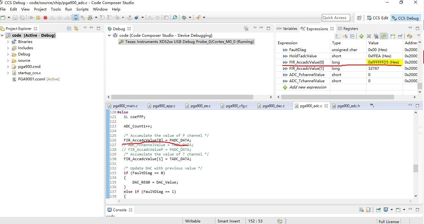
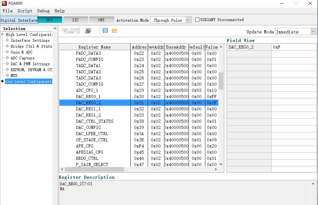
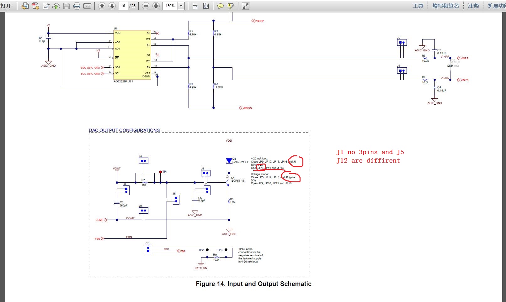
Register shows pressure data has been collected, but the ammeter or voltmeter still can not output data. I can only change the output voltage or current value by the drawing of write operations to. DAC output can not change with the ADC samples. How to configure. thank you very much.
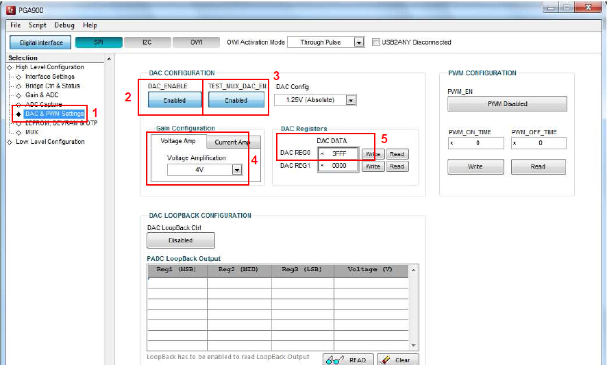
  • Hi John, that is correct. The PGA900 is an open core device, meaning the M0 is not programmed, it needs to be programmed by the customer. It is in the M0 where the compensation equation that relates the DAC output the ADC input is implemented. Without programming the M0, the only way to change the analog output is by writing directly to the DAC following the process you indicated.

    There is a reference firmware for the M0 that could be used as a starting point for what you want to achieve, but it needs to be modified. You can find the firmware at the product folder.

    http://www.ti.com/lit/zip/sldc010

    Thanks,

    JV

  • i have downloaded the PGA900.out and debug . But the Padc samples display a wrong data,and only change 0xFFFF FFD4 or 0xFFFF FFD6 ,no matter the  input's press is how to change by the press generater . however ,i can get the Pdata by PGA900 GUI . just like my question  

  • Hi John, it seems like you are reading a very small negative value in the PADC registers. Based on this:
    1. Are you enabling the bridge voltage in the firmware by configuring the BRDG_EN register/
    2. Are you setting all the proper muxes for the PADC (PGAIN_OPEN, TEST_MUX_P_EN and PADC_EN?

    Thanks,

    JV
  • thanks for your reply . i have got the PDATA , I have a PGA900EVM and configure it for 4- 20mA acorrding to the PGA900EVM guide , but the DAC cannot get 20mA,only 15.xx mA by setting the DAC_REG0. No matter ,the  DAC_REG0 was setted 0 to 0x3FFF ,the value is less than 20mA . can you give me a good configured PGA900GUI's configuration and  good configuration codes of PGA900 ( CCS project)  ?

  • Hi JV , I tried to configure Voltage Mode and the result and function are very satisfied . But still cannot 4~20mA in current mode .and i sure the configuration of the PGA900EVM is right acorrding to the PGA900 guider , and I think the guider have some problems ,please tell me how to connect the pins .  Should I connect the PINs acorrding which ways    ?

  • John, yes, we are aware of this typo in the user's guide and we are in the process of updating it. Table 2 is correct, the typos are in the dotted box in Figure 14 of the schematic. Therefore, please follow Table 2 settings for the jumpers.

    Thanks,

    JV