This thread has been locked.

If you have a related question, please click the "Ask a related question" button in the top right corner. The newly created question will be automatically linked to this question.

Questions about OPT9221/OPT8241 : High Ambient setting

Other Parts Discussed in Thread: OPT9221, OPT8241, OPT8320

Hi,

I have got some questions about "High Ambient" process of OPT9221/8241 from my customer.

Could you tell me your advice?

Q1) Shutter function

OPT8241 has a shtter function to make the sensor work under sunlight. (prevent from saturating)

Could you tell me how does it work?

There is no description about the shutter on the datasheet.

And do you have something evaluation data when this function is ON/OFF?

Q2) High Ambient control

To use OPT9221/8241 under the conditon of "High Ambient" like under the sunlight, we need to control "Integration duty cycle", "Sub-frame number"

and "Shutter", I think.

That is to say,

 - By reducing the duty cycle, we can prevent the sensor from surturating.

 - By increasing the number of "Sub-Frame" (= increasing intergration time), then we can improve the S/N.

 - As the reset is done by every "Quad stage", the charged data of the previous sampling is removed and then S/N is also improved.

Is my idea correct?

But I do not understand how is the shutter doing role in data acquisition stage...

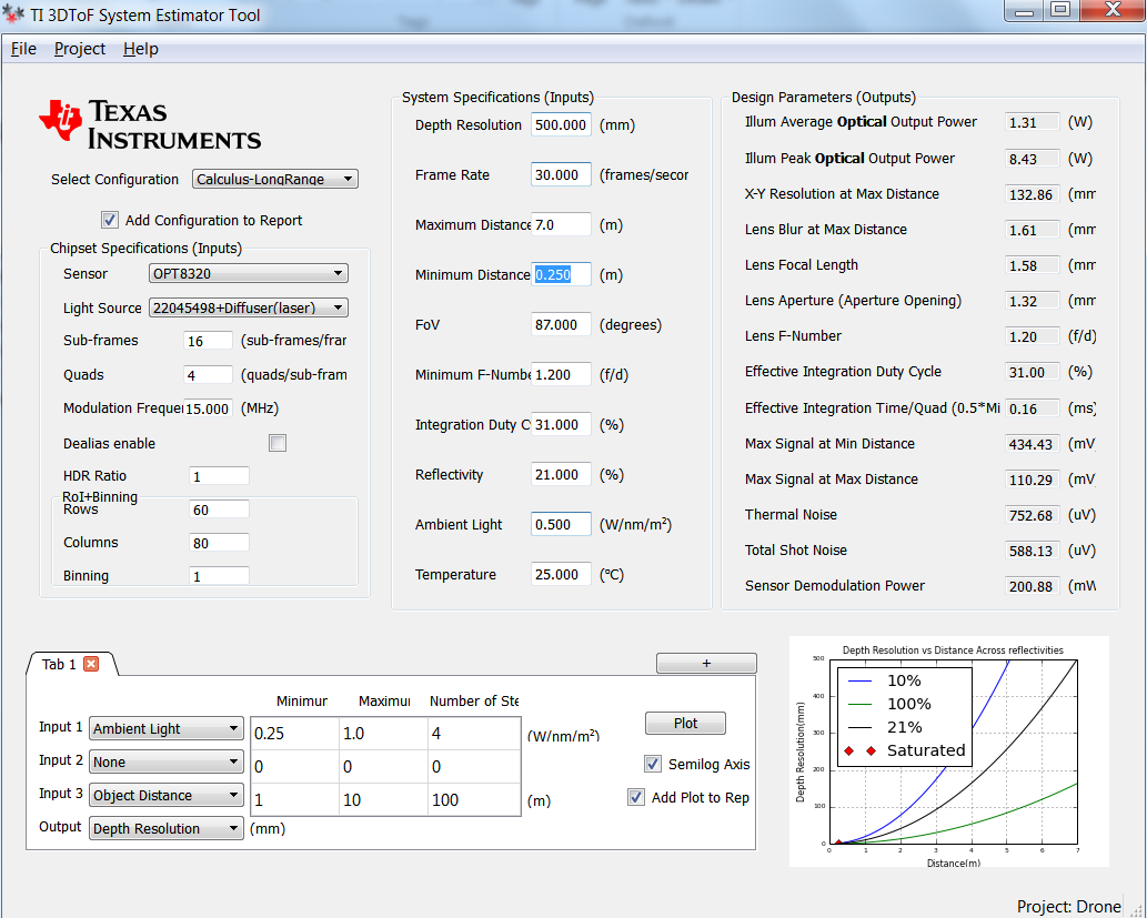
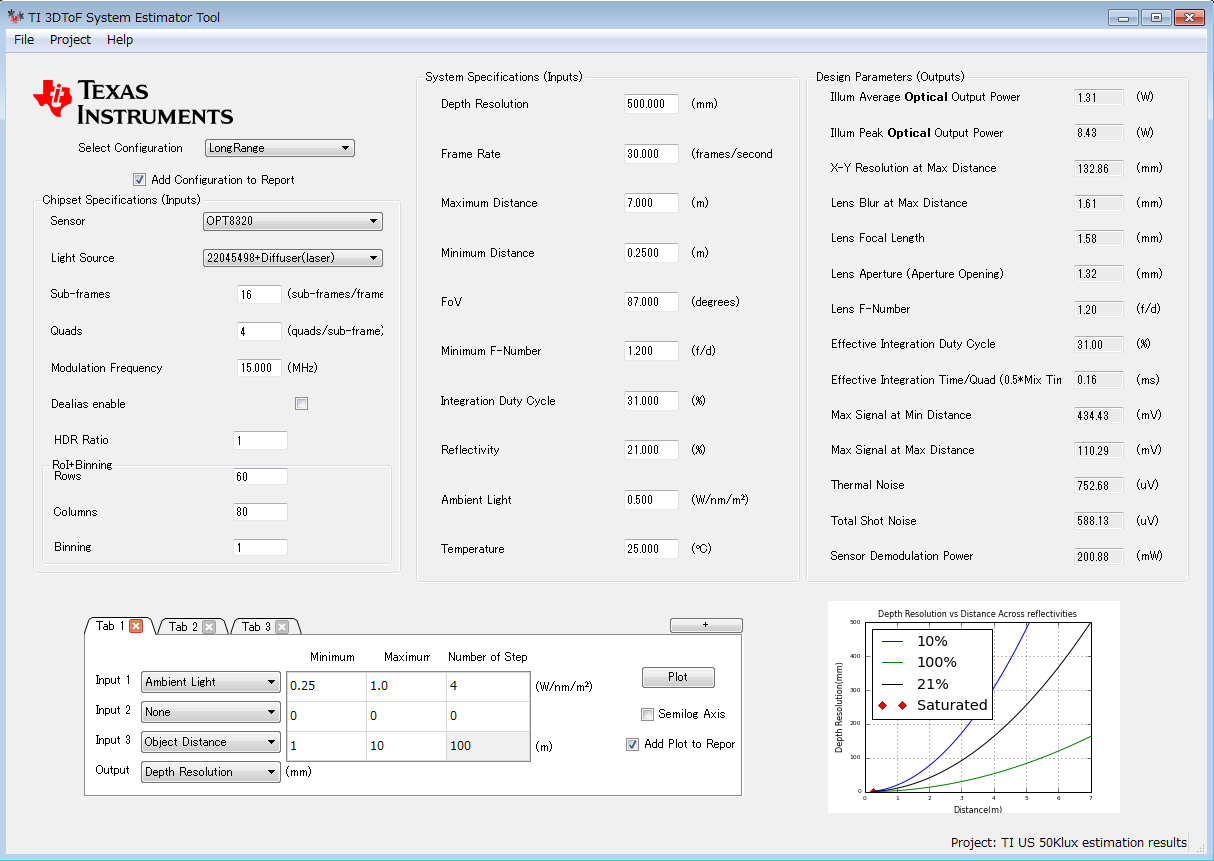
Q3) SYSTEM ESTIMATOR TOOL

About the tool, the "Ambient light" setting is "1.000W/nm/m2" by default under the "High Ambient" configuration as below.

Can I understand that this value is the same as "100K lux" as under the strong sunlight?

Q4) The relation between "Frame", "Sub-Frame" and "Quads"

 Q4-1) Could you provide me the timing chart of these signals to understand well?

 Q4-2) I do not understand well the relation of these signals, to my regret.

           I suppose, as a result, the number of "total Quads/Frame" is important.

           For example, the total quads number of both case1 and case2 are same, 160.

           What is the different between both cases?

               case1) Frame rate : 10, Sub-Frame : 4, Quads : 4

               case2) Frame rate :   5, Sub-Frame : 8, Quads : 4 

Q5) evaluation data of EVM

Do you have anything measurement data (High Ambient and not high ambient) by using EVM to support to design?

Thank you very much for your support!

Best Regards,

  • Suzuki-san,

    Please give us a couple of days to answer your question in detail.

    Regards
  • Hi Bharath-san,

    Thank you for you support and sorry for not easy my questions to understand.

    Let me wait for your reply.

    Regards,

  • Hi Bharath-san,

    Would you kindly answer for me about my questions?
    It's OK to answer the questions which are not needed NDA.

    Regards,
  • Q1 – Shutter Operation

    Shutter operation can be used to control the exposure to ambient light. The shutter switch separates the charge storage node from the pixel charge collection node. The shutter can be programmed to become inactive (switch is on) at the start of integration and become active (switch is off) at the end of integration time to avoid collection of unwanted ambient light during the sensor readout. The behavior of the shutter switch is shown below (for more information regarding quad state , refer section7.3.3.1 Basic Frame Structure in OPT9221 data sheet).


    Shutter Operation


    OPERATION

    QUAD STATE

    RESET


    INTEGRATION

    READOUT QUAD

    DEAD TIME

    State of the shutter switch with the shutter operation enabled (default)


    On

    On

    Off

    Off

    State of the shutter software with the shutter operation disabled

    On

    On

    On

    On


    Register setting for shutter


    Q2 – High Ambient operation

    Your understanding regarding reducing integration duty cycle and increasing sub frames is correct. As explained in Q1, shutter helps to improve the performance in high ambient conditions.

    Increase the number of sub-frames and reduce the integration time per sub-frame to collect the same amount of signal light while avoiding pixel saturation. You can also Increase the illumination peak power and reduce the integration time to reduce the ambient light collected while keeping the amount of signal light collected the same.


    Q3 - About the ambient light value in System estimator tool

    The spectral content of 850nm light at 100k lux sunlight is approximately 1W/nm/m^2

    Q4 – 1 – Frame rate, sub frames and quads

    Frame rate measures the rate at which data is given out by the TFC to the software. It corresponds to the same frame rate term used in digital video cameras.

    Internal to the TFC, each frame is divided into a similar set of measurements called sub-frames, as shown in section 7.3.3.1 of OPT9221 datasheet. Each sub-frame has all the measurements necessary for phase computation. Multiple sub-frames are used to overcome the limitations of pixel saturation, and therefore enhance the dynamic range of the system. Sub – frame data is internally averaged to form each frame data.

    Now within a sub – frame, the relative phase between the illumination and sensor modulation signals are changed. Quads denote the no of steps of such phase changes and by how much they are changed. For example quad=4 means within a sub - frame, the relative phase between illumination and sensor modulation signals are changed in 4 steps and they are 0⁰,90⁰,180⁰ and 270⁰.

    The main point to note here is that sub - frames are identical whereas quads are not.

    Q4 -2 –

    In both cases quad rate is same and equals 160 (frame rate *sub - frames*quads). Hence from a saturation point of view both are same .

    Now the selection of case 1 or case 2 depends on the application. Here case. Case 1 with higher frame rate can be used in applications where data latency is more important like tracking moving objects. Here you will get more data outputs from the TFC. But average and optical power will be more in this case.

    Q5- experiment data for high ambient ( 50k lux ) with OPT8320


    Simulation data using system estimator tool

    Summary of results -

    Distance

    Depth resolution

    1.2m

    ~2cm

    3m

    ~16cm

    6.5m

    ~58cm

    7.5m

    ~65cm


    As can be seen from the above results, actual results and simulations match very closely.


    Comments about minor differences in actual settings -

    Peak illum power : ~8W (instead of the 8.43W shown in the simulation)

    Average illum power : 1.25W (instead 1.31W shown in the simulation)

    Reflectivity : ~50% (instead of 21% in the simulations. This has been done because lens used had poor transmissivity. Therefore, it is equivalent to reducing the reflectivity in the simulations)


    Sun : Show below - (Probably somewhere between 50 - 60klux) Cloud cover was quite thin.


  • Hi Nithin-san,

    Thank you so much for your detail and kind reply !!

    I understood well.

    But let me confirm a few points as below?

    I tried to use estimation tool to confirm your settings.

    The followings are my setting display and result.

     Are both setting and result correct?

    And the following your data is an actual data by using OPT8320, right?

    Did you compare this data with estimator's result (Green data = Ambient light 0.5)?

    Thanks and Best Regards,

  • Hi Takumi San

    Both the setting and the results are correct. Data given in the table is the actual data by using OPT8320.
    Both simulation data and actual results are comparable. Actual conditions generally vary from simulation conditions. So kindly use the system estimator as a starting point and design with a tighter requirement in the simulation to allow for this margin.

    Thanks and regards
    Nithin
  • Hi Nithin-san,

    Thank you so much!

    I unerstood.

    Regards,

  • Hi Nithin-san,

    Let me ask you one question about the meaning of "Depth Resolution".

    There is an item of "Depth Resolution" on the estimator tool as above.

    In this case, the resolution value is set to "500.000 mm" (=50cm).

    About the meaning, I understood that the resolution is "max error" distance between object and camera when the true distance is 7m.

    That is to say, the distance TOF camera measured is from 6.5m to 7.5m.

    Is this correct?

    And your results as below, the "depth resolution" you said is the same meaning of the estimation tool, right?


    So, in case of distance is 7.5m, the max error is 65cm. (the distance is measured between 6.85m to 8.15m)

    Thank you for your support.

    Best Regards, 

  • Hi Nithin-san,

    Could you tell me if my idea is correct?
    Thanks!
  • Hi Suzuki-san,

    Depth resolution means the standard deviation in depth data .

    Thanks and regards
    Nithin
  • Hi Nithin-san,

    Thank you for your reply!

    I understood.

    Regards,

  • Hi Nithin-san,

    Thank you very much!

    Regards,