This thread has been locked.

If you have a related question, please click the "Ask a related question" button in the top right corner. The newly created question will be automatically linked to this question.

LDC1612 not awaking from sleep mode

Other Parts Discussed in Thread: LDC1612, LDC1614

Hello,

I assembled two LDC1612 IC on my custom board

Initially when assembled they were working, but 1 IC's among entered sleep mode and is not able to exit from it.

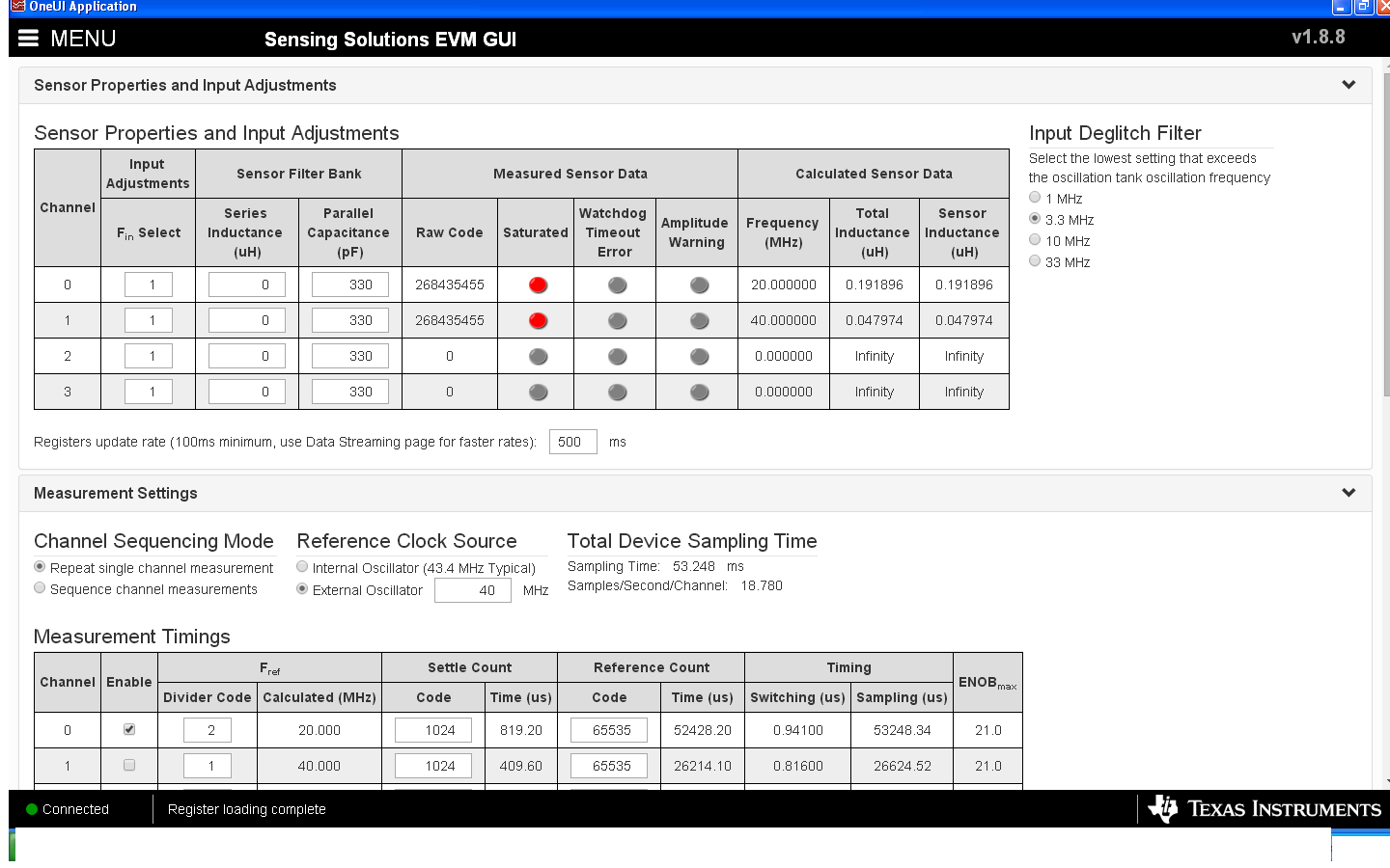
In that particular board i am able to set the required value for all registers except for config register(0x0A). every time i set the value to 01E10, it doesn't set, it resets back to 0x00. The IC accepts the value 0X3E10 only.

What might have caused the issue?? And how to get out the this problem??

Regards

Yeshwanth Kumar J  

  • Hello Yeshwanth,

    register 0x0A is not the config register but the RCOUNT register for Channel 2 of the 4-channel LDC1614. The dual channel LDC1612 only has channels 0 and 1, and therefore this register is reserved and can not be changed.

    Sleep mode is controlled by bit 13 of 0x1Ah. Valid register values for this register would be 0x1E01 (active) or 0x3E01 (sleep). Please do not change the two LSBs of this register either; they are reserved and should always be set to 0 (Bit 1) and 1 (Bit 0)

  • Hello Ben Kasemsadeh,
    My mistake, I had typed it wrong.

    I indeed used the address 0x1A for my settings. and I found the issue. very time i set the value to 01E10, it doesn't set, it resets back to 0x00. The IC accepts the value 0X3E10 only.

    Any means to wake up the controller using HW settings??


    regards
    Yeshwanth Kumar J
  • Hello Yeshwanth,

    • What is the logic level on the SD pin? It must be low (active) to be able to configure the device.
    • Are you able to write and read back the correct value from other registers, for example register 0x08 (RCOUNT)?
    • Also, are you using TI GUI/Firmware? If yes, please let me know which GUI rev and which Firmware rev you use.

  • Hello Ben,
    Sorry for my late reply.
    I tried to simulate the same by connecting my custom board with Ti EVM board, so it took time. But it did nt waork.
    I am using my own custom board. I read the data in console mode.
    The SD pin is connected to GPIO pin. The pin is pulled down(via SW command). I am able to write the register value and I am also able to read it back .
    I also encountered 1 more case where in the board gives me output as "0", but I am able to read the device ID and Manufacturing ID.

    So out of the 3 boards I have assembled.
    in board 1 I am not able to come out of sleep mode. But i am able to set other registers.
    In board 2 I am able to set all register values including config, but I get the data as "0".
    in board 3 I am able to read the data.
    In all the 3 board same FW i am using.
    I am unable to crack what's wrong.
    I even tried to scope the clk pin in all 3 boards. they all are same.

    Yeshwanth Kumar
  • Hello Ben,

    I was able to connect  my board 2 with TI EVM and I found that the channels are shown as saturated.

    The data loged also is static, it doesnt detect any object as well

  • Hello Yeshwanth,
    1) do the EVMs work unmodified with TI software and the latest TI firmware?
    2) can you try to assert SD and then de-assert SD before attempting to wake up the device from sleep?
    3) the GUI shows that the calculated sensor frequency exceeds the maximum supported frequency. This means that either the firmware is old, the connected sensor is invalid (violates datasheet specification), or that I2C communication is faulty.
  • Hello Ben,
    The evm works when reassembled with actual TI board(LDC1614 and coil unit)
    2) I tried with asserting SD and de-Asserting SD, it did not work. May be the IC is at fault.
    3) I have cross checked my calculations they do match with the requirement, where else could I be going wrong ?? Could the method of soldering be the cause of malfunctioning??


    Thanks
    Yeshwanth Kumar J
  • Hello Yeshwanth,
    I don't believe that the IC is at fault because it worked when you re-connected it to the TI EVM. The sensor doesn't seem to be the issue either, you should be able to get the part into and out of sleep mode regardless of the sensor.

    Please compare schematics and probe nearby components of both your PCB and the EVM with a scope to narrow down the problem.
    Also, please verify that I2C pull-up resistor values, protocol and timing are correct, and compare with the EVM.