This thread has been locked.

If you have a related question, please click the "Ask a related question" button in the top right corner. The newly created question will be automatically linked to this question.

TDC7200 Input Impedance

Other Parts Discussed in Thread: TDC7200, TDC7200EVM

I'm using a function generator for the input START/STOP signal.

It has a 50ohm termination.

I want to determine the input pulse voltage value of START/STOP signal.

But I think it's not mentioned input impedance in the data sheet.

Could you tell me TDC7200 Input Impedance?

  • Hello,

    The input resistance of the TDC7200 pads is 400 ohm so the function generator may need to be adjusted to provide optimal output impedance.

    Please refer to TDC7200 IBIS model (link below) if you need more accurate model of the input impedance.

    http://www.ti.com/lit/zip/snam176

    Thanks,
    Vishy

  • Vishy,

    I refered to the IBIS model but, I'm afraid we can't know input impedance from this.

    I tested TDC7200EVM and inputed DC3.3V from J5 and measured voltage level of TP2 (before R2) / START PIN (after R2).

    The value is almost the same (3.3V) between TP2 and START PIN. It means input impedance is much higher than 400 ohm.

    If input impedance is 400 ohm, START PIN voltage should be about 1.47V.

    So, I think input impedance is at least a few hundred kilo ohm.

    Could you tell me if I missed something.

    Thanks
  • Tomoya,

    I checked about this. The pads resistance 400ohm is in series and the input impedance is actually very high (Hi-Z) like you mention. Thanks for cross checking.

    I use a Tek AFG3102 and under the output menu you can change the output load selection. With a 50 ohm source and a Hi-Z load the output level on the screen will show as 1 Vpp but the measured output into a Hi-Z will be 2 Vpp. If you were to change the selection to Hi-Z then the screen would read 2 Vpp the same as the measured value.

    Thanks,
    vishy
  • Tomoya-san,

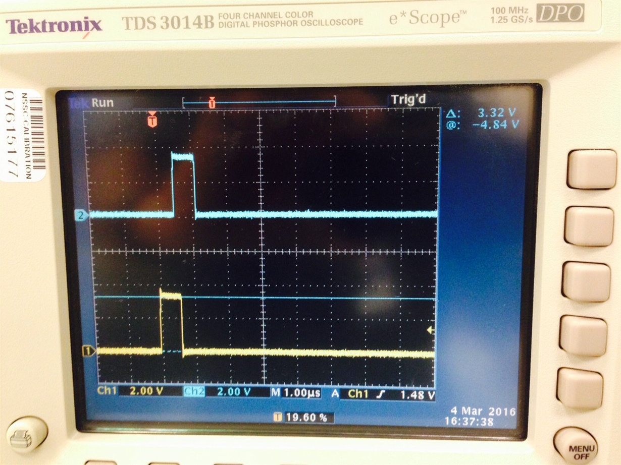
    I enclose  pictures of AFG3102 settings (with load Hi Z selection) and a scope shot. Channel 1 is connected to TDC7200 Start input and Channel 2 is connected to TDC7200 Stop input. The scope measured value matches the AFG settings.

  • Vishy,

    Thanks for the answer and information about AFG3102 settings.
    I can determine the input level.

    Though freq is 40kHz in the TDC7200EVM User’s Guide, your setting is 320kHz.
    Could you tell me why if there is a reason?

    Thanks
  • Tomoya-san,

    No particular reason for 320kHz. I just used the same setting from another experiment.

    Thanks,

    Vishy